Download
1 / 46
490 likes | 1.18k Vues
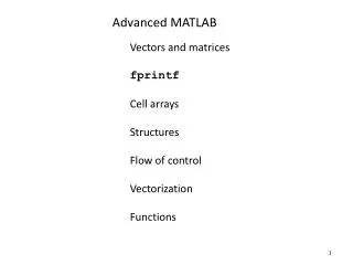
Advanced MATLAB Summer 2018 Design of digital FIR filters using the Windowing Technique. Behrad TaghiBeyglou Department of Electrical Engineering Sharif University of Technology. Design of Digital Filters. LTI Systems h(n). FIR. IIR. Determine coefficients of

E N D
Advanced MATLABSummer 2018Design of digital FIR filtersusing the Windowing Technique BehradTaghiBeyglou Department of Electrical Engineering Sharif University of Technology
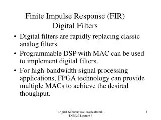
Design of Digital Filters LTI Systems h(n) FIR IIR Determine coefficients of h(n) [or P(z) and Q(z)] With rational transfer function No rational transfer function BehradTaghiBeyglou, EE, SUT, 2018
Design of digital filters • Design Stages • Specifications Application dependent • Design h(n) Determine coefficients of h(n) • Realization Direct form I,II, cascade and parallel • Implementation Programming in Matlab/C, DSP, ASIC,… • Design of FIR filters • Windowing BehradTaghiBeyglou, EE, SUT, 2018
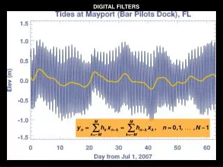
Motivation: impulse response of ideal-low-pass filter • IDTFT of ideal low-pass filter: BehradTaghiBeyglou, EE, SUT, 2018
Motivation: impulse response of ideal low-pass filter Multiply by a rectangular window • It can be shown that if we have a linear-phase ideal filter and we multiply it by a symmetric window function, we end up with a linear-phase FIR filter. BehradTaghiBeyglou, EE, SUT, 2018
Incorporation of Generalized Linear Phase • Windows are designed with linear phase in mind • Symmetric around M/2 • So their Fourier transform are of the form • Will keep symmetry properties of the desired impulse response • Assume symmetric desired response • With symmetric window • Periodic convolution of real functions BehradTaghiBeyglou, EE, SUT, 2018
Design of FIR filters using windows • The steps in the design of FIR filters using windows are as follows: • Start with the desired frequency response results in the sinc function in time domain • Compute • Determine the appropriate window function w(n) • Calculate A finite-length window function BehradTaghiBeyglou, EE, SUT, 2018
Desired frequency response • Two properties should be considered: • 1) The amplitude is unity in the pass band and it is zero in the stop band: • 2) The phase is linear: BehradTaghiBeyglou, EE, SUT, 2018
Example: Design of a high-pass FIR filter • First, we have to decide on the type of the filter. • Assume Type I filter • (linear-phase) BehradTaghiBeyglou, EE, SUT, 2018
Example: Design of a high-pass FIR filter IIR filter BehradTaghiBeyglou, EE, SUT, 2018
Example: Design of a high-pass FIR filter • It is a high-pass FIR filter with 7 taps that approximates the high-pass IIR filter. • How can we quickly check that the resulting FIR filter has the desired properties that we were looking for? (i.e., it is a high-pass linear-phase filter)? BehradTaghiBeyglou, EE, SUT, 2018
Reminder: DTFT Pairs HosseinSameti, ECE, UBC, Summer 2012 Originally Prepared by: MehrdadFatourechi,
Windowing in frequency domain • What condition should we impose on W(ω) so that H(ω) looks like Hd(ω) ? • Impulse function in the frequency domain, means an infinitely-long constant in the time-domain • Larger window means more computation BehradTaghiBeyglou, EE, SUT, 2018
Windowing in Frequency Domain • Windowed frequency response • The windowed version is smeared version of desired response • If w[n]=1 for all n, then W(ej) is pulse train with 2 period BehradTaghiBeyglou, EE, SUT, 2018
Rationale for the shape of the filter Ideal filter RectangularWindowfunction (Oppenheim and Schaffer, 2009) BehradTaghiBeyglou, EE, SUT, 2018
Filter Specifications Pass-band: Stop-band: Pass-band ripple: Stop-band ripple: Transition width: (Oppenheim and Schaffer, 2009) • What is the ideal situation? BehradTaghiBeyglou, EE, SUT, 2018
Filter Specifications BehradTaghiBeyglou, EE, SUT, 2018
Observations Width of transition is not sharp! • The width of transition depends on the width of the main lobe of the window. • Ripples in the passband / stopband are proportional to the peaks of side lobes of the window. BehradTaghiBeyglou, EE, SUT, 2018
Controlling the width of the main lobe • Q: How can we control the transition width (size of the main lobe)? • A1: using the size of the window Uncertainty principle BehradTaghiBeyglou, EE, SUT, 2018
Controlling the width of the main lobe • Q: How can we control the size of transition width (size of the main lobe)? • A2: Shape of the window; in other words, windows with a fixed size that have different shapes can have different main lobe width. • Rectangular window Smallest; and Blackman largest main lobe width BehradTaghiBeyglou, EE, SUT, 2018
Controlling the peak of the side lobe • Q: How can we control the peak of the side lobes so that we can get a good ripple behavior in the FIR filter? • A: using the shape of the window BehradTaghiBeyglou, EE, SUT, 2018
Controlling the peak of the side lobe • Q: Can we control the peak of the side lobes by changing the size of the window? • A: It can be shown that changes are not significant. BehradTaghiBeyglou, EE, SUT, 2018
Demonstration using Kaiser window BehradTaghiBeyglou, EE, SUT, 2018
Properties of Windows • Prefer windows that concentrate around DC in frequency • Less smearing, closer approximation • Prefer window that has minimal span in time • Less coefficient in designed filter, computationally efficient • So we want concentration in time and in frequency • Contradictory requirements • Example: Rectangular window BehradTaghiBeyglou, EE, SUT, 2018
Rectangular Window • Narrowest main lobe • 4/(M+1) • Sharpest transitions at discontinuities in frequency • Large side lobes • -13 dB • Large oscillation around discontinuities • Simplest window possible BehradTaghiBeyglou, EE, SUT, 2018
Bartlett (Triangular) Window • Medium main lobe • 8/M • Side lobes • -25 dB • Hamming window performs better • Simple equation BehradTaghiBeyglou, EE, SUT, 2018
Hanning Window • Medium main lobe • 8/M • Side lobes • -31 dB • Hamming window performs better • Same complexity as Hamming BehradTaghiBeyglou, EE, SUT, 2018
Hamming Window • Medium main lobe • 8/M • Good side lobes • -41 dB • Simpler than Blackman BehradTaghiBeyglou, EE, SUT, 2018
Blackman Window • Large main lobe • 12/M • Very good side lobes • -57 dB • Complex equation BehradTaghiBeyglou, EE, SUT, 2018
Frequency response of some popular windows (M=50) rectangular Bartlett Hanning Hamming Blackman BehradTaghiBeyglou, EE, SUT, 2018
Peak Approximation Error • Approximation Error, defined in passband and stopband. • Peake Approximation Error is the maximum value of BehradTaghiBeyglou, EE, SUT, 2018
Comparison of different windows BehradTaghiBeyglou, EE, SUT, 2018
Good design strategy Main lobe Shape of the window width of the window Main lobe Side lobe Good design strategy: 1) Use shape to control the behavior of the side lobe. 2) Use width to control the behavior of the main lobe. BehradTaghiBeyglou, EE, SUT, 2018
Kaiser window Zeroth order modified Bessel function of the first kind Number of taps Parameter to control the shape of the Kaiser window and thus the trade-off between the width of the main lobe and the peak of the side lobe. BehradTaghiBeyglou, EE, SUT, 2018
Demonstration of Kaiser window M=20 BehradTaghiBeyglou, EE, SUT, 2018
Demonstration of Kaiser window BehradTaghiBeyglou, EE, SUT, 2018
Comparison with popular windows BehradTaghiBeyglou, EE, SUT, 2018
Design Guidelines using Kaiser window • Calculate the transition bandwidth • Calculate • Choose • Choose BehradTaghiBeyglou, EE, SUT, 2018
Example: Design of LPF using Kaiser window Specs: BehradTaghiBeyglou, EE, SUT, 2018
Example: Design of LPF using Kaiser window Specs: Type II filter Use Bessel equation to get w(n) BehradTaghiBeyglou, EE, SUT, 2018
Example: Design of LPF using Kaiser window BehradTaghiBeyglou, EE, SUT, 2018
Example: Design of LPF using Kaiser window Q: Does it satisfy the specs? BehradTaghiBeyglou, EE, SUT, 2018
Summary • Windowing method is a fast and efficient solution to design FIR filters. • Using Kaiser windows, the window can be chosen automatically. BehradTaghiBeyglou, EE, SUT, 2018