Download
1 / 62
620 likes | 780 Vues
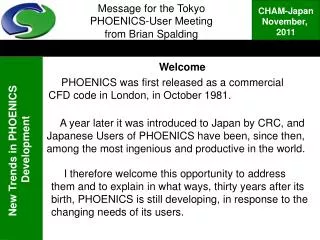
Welcome PHOENICS was first released as a commercial CFD code in London, in October 1981. Message for the Tokyo PHOENICS-User Meeting from Brian Spalding.

E N D
Welcome PHOENICS was first released as a commercial CFD code in London, in October 1981. Message for the Tokyo PHOENICS-User Meetingfrom Brian Spalding A year later it was introduced to Japan by CRC, and Japanese Users of PHOENICS have been, since then, among the most ingenious and productive in the world. I therefore welcome this opportunity to address them and to explain in what ways, thirty years after its birth, PHOENICS is still developing, in response to the changing needs of its users.
The needs of PHOENICS users are not all the same. In the past, CHAM has tried to satisfy all by means of a single data-input module, the VR-EDITOR, operating in graphical interactive mode. Message for the Tokyo PHOENICS-User MeetingSummary There are two drawbacks: • VRE presents too manychoices for some users; and • it cannot activate all PHOENICS capabilities. Now therefore CHAM has added new input procedures which meet the differing needs of five different classes of user. These will now be described.
Recognising five different groups of users: 1. those needing Gateways PHOENICS is a General-Purpose package; but most of its users have specialpurposes. • User Group 1 wants easy-to-use simulation-and-design software for particular processes, e.g.: • heat exchangers (shell-and-tube, plate, air-cooled… ) • chemical reactors (CVD, stirred-tank, fluidised-bed...) • environmental flows (wind-farm, city pollution, fires… ) • pumps and fans (gear-wheel, bladed, piston-cylinder... ) To this group CHAM offers special-purpose stand-alone packages, accessed through application-specific Gateways.
Recognising five different groups of users (continued)2. Gateway Creators CHAM has itself created several gateways; and it will create any more which customers commission. But users of Group 2 are those who wish to create their own. To this group CHAM offers: • Examples of parameterised relational-data-input files; • explanations of these, and assistance, in the creation of new ones. • PRELUDE, which automatically converts these into Gateway packages which exactly suit the needs of the defined Group-1 users.
Gateways enable users easily to access existing features of PHOENICS; but Group-3 users wish involve features which do not yet exist, for example: unusual geometries not fitting structured grids; materials with unusual thermo-physical properties; never-before-tried turbulence models; or novel equation-solving algorithms. To this group CHAM offers: Recognising five different groups of users (continued):3.Those requiring new features • In-Form which adds new features without new Fortran or C coding; • advice and assistance for those who request it; • a library of cases for copying.
PHOENICS can be used for learning about fluid mechanics, heat transfer, chemical reaction, solid mechanics and their engineering and environmental effects. For Group-4 members, i.e. students and teachers, CHAM offers: Recognising five different groups of users (continued)4. students and teachers • PHOENICS-For-Teaching, which comprises: • an extremely-simple interface; • a teacher mode which creates cases to be run; • a student mode which facilitates running of cases; • automated calculation and display of results; • multi-language text capability; • an organisational framework which enables contributors to collaborate internationally.
Experienced users of PHOENICS may require no fundamental changes. As Group 5 they desire only that: all familiar features should continue to exist; changes should be only in greater speed of operation, richness of options, freedom from failures. To this group CHAM offers: Recognising five different groups of users (continued)5. Already-experienced users • Continued development to ensure that the VR Editor, the Earth solver, the VR Viewer, PHOTON. POLIS, Parallel Operation, etcetera remain in use and are improved in detail. • Free-of-charge support to maintained users.
Developments relating to Group 1:An example: the hen-house gateway • Let us suppose that the task is to predict air temperature, humidity and composition within a hen-battery building. • It is a CFD problem; so PHOENICS can be used to solve it. But how? • Input data include the geometry (what is where); the production rates of heat and pollutant from each cage; the air-supply rate and temperature. • Free (gravity-induced) convection is as important as forced convection.
. CFD for the hen-houseEase of use is essential • Specialists in the animal-production-environment know little about CFD. They need programs devised especially for them. • Data input should be made easy, so as to save time and minimise mistakes. • Simulation results should be presented in a way which makes them easy to inspect and interpret.
The CFD-Gateway concept;What a hen-house gateway might look like Picture of Gateway menu panel with part of a battery of chicken- cages in its graphics window. Button rows are standard for all gateways. Clicking on items in the ‘object tree’ reveals what is specific to this gateway..
The Gateway user will supply, via menu boxes, the data which he knows about e.g.: size, number and arrangement of cages; location, temperature and flow rate of air supply; attributes of chickens (heat output, oxygen consumpton, air-pollution rate). Developments relating to Group 1:input data which the user will supply • The Gateway user will not be asked to choose: • turbulence models, • grid type or fineness; • sweep number; • relaxation and other numerical parameters. The Gateway creator (User-Group 2) will have already built choices into the Gateway-design script.
The CFD-Gateway concept;Looking at the results After its user is satisfied with the input data, clicking the ‘run’ button launches the simulation and displays results as velocity vectors (right) or contour displays (left) on accordance with pre-set orders, or the user’s menu-expressed wishes. The left-hand picture shows the SMEL (odour) contours.
The CFD-Gateway concept;What the Group-1 user would learn • Printed numerical results of interest to the user might include: • locations and maximum values of temperature, air-pollutant, etcetera; • electric power and heat input needed for specified conditions. By varying the input conditions and observing the changes in results, the user would thus be enabled to determine how to optimise hen-house design and operation. Thus the animal-production specialist could become, without expensive training, a user of PHOENICS and CFD.
Second user Group:The Gateway Creators Users of Group 1 are able to benefit from CFD when suitable PHOENICS Gateways have been prepared for them by someone else. By whom? By Group-2 users, who have learned how to create Gateways. Managers please note:Personnel for Groups 1 and 2 utilise different skills, and convey different benefits. A well-balanced team requires persons of both kinds.
To create a new gateway, one need not start from scratch; for the PRELUDE package exists, with ready-to-use general framework and customising tools. Developments relating to User Group 2:how to create the hen-house gateway Here is shown its standard top-menu bar. These provide the frequently-required functions of opening cases, introducing or deleting objects, selecting them for attribute modification, running simulation calculations, etcetera. Tutorials exist which explain these.
Developments relating to Group 2: Objects and their attributes Here is shown an object tree which might be created for a hen-house gateway. Clicking on an item enables its attributes to be reviewed, and edited if need be. These items control results-display items, viz stream-lines; and ‘cutting planes’ for contours and vectors; and these the in-and outflow of ventilating air. Here are the stored and solved-for 3D variables. Note that SMEL, of which chickens are a source, is one of them.
Developments relating to Group 2;Inserting an array of cage objects It would be would be tedious to introduce the cages one by one; so PRELUDE offers an ‘array’ facility seen below. Note that expressions can be entered. Here ‘shed’ is the (highlighted) name of the array. ‘Cage’ is the name of the object arrayed.
Comparison ofVR-Editor and PRELUDE The PHOENICS VR Editor facilitates the setting up only of single-instance flow-simulation scenarios. For example, only numbers can be typed into its menu boxes, thus; but not expressions as in PRELUDE: VRE can display scenarios created by PRELUDE. But it lacks PRELUDE’s array-specification feature. PRELUDE.is therefore the preferred user interface for PHOENICS.
Just as VRE receives instructions from Q1 written in PHOENICS Input Language (i.e. PIL), PRELUDE receives instructions from Q3 written in PRELUDE Script Language (i.e. PSL). Developments relating to Group 2:what the Gateway-creator must do Group-2 users can learn PSL, and so write Q3 files: or they can express their needs in parameterised Q1 (i.e. PIL) files. Then PRELUDE can translate these into Q3 files. Therefore Group-2 users need not learn PSL. Tutorials explain how to write parameterised Q1s; and there exist input-file-library examples and a power-point presentation.
Developments relating to Group 2:data input How PRELUDE, Q1, Q3, VRE, etc fit together is shown below. Gateway creators express choices of turbulence models and numerical parameters via PIL in Q1. They must also make wise choices about whether (or when) to use Space-Averaged or Detailed-Geometry CFD, both of which PHOENICS can supply. What are SACFD and DGCFD? See next slide.
Space-Averaged- and Detailed-Geometry CFD for heat exchangers SACFD DGCFD Tubes in a heat exchanger are too numerous for DGCFD to beused for the whole equipment; so formulae for volumetric heat transfer are used, derived from results of DGCFD applied to parts of the tube bundle. The DGCFD results are obtained first. Then the results are parameterised for use later in SACFD.
DG-CFD as the extrapolator from experimental data Question: But there exist experimental data for volumetric heat-transfer and friction coefficients of tube bundles, as shown on the right. Why not use them? Answer: They should be used; but there are never enough of them; and they seldom reveal the effects of, say, property variations with temperature. So they are best used for calibrating DG-CFD simulation models.
SA- and DG-CFD;applied to the hen house Combined SA and DG can be applied to hen-house simulation simply by setting the array parameters to 1,1,1, with the result on the right: Now all the computational cells can be concentrated in the smaller domain surrounding the single cage; so transfers of heat, matter and momentum from hen to air can be more accurately simulated. Doing so at various Reynolds numbers and wind angles allows formulae to be developed which can be used in whole-hen-house SA-CFD simulations.
Detailed-geometry CFD;The pecking chicken, 1. PRELUDE can also be used for moving objects Here is a chicken, with thedetailed-geometry grid set up for a time-dependent simulation.
Detailed-geometry CFD;The pecking chicken, 2. PRELUDE enables the motion of the chicken to be prescribed by way of formulae. Here is the formula to be used for describing its periodic pecking motion. The PHOENICS MOFOR (i.e. MOving-Frame- Of Reference) technique is activated.
Detailed-geometry CFD;The pecking chicken, 3. Here is an animated view of some results of simulation. Note the air-velocity vectors and surface -pressures. This shows (more for entertainment than necessity) what can be done with detailed-geometry CFD; hen-house designers need not go so far!
The Moving-Frame-of Reference Technique; some details MOFOR consists of two features, namely: (1) description of the motion; and (2) Creating the response of the fluid to that motion. The first uses a technique borrowed from the motion-picture industry (‘Titanic’, ‘Babe’): a ‘MOF file’ is generated, as shown on the next slide. It dictates the translations, rotations and corresponding velocities and accelerations of torso and limbs. The second exploits whatever source-and-sink mechanism is present in the underlying CFD solver (here, of course, PHOENICS).
The MOF file generated by PRELUDE for the pecking hen Below is the first part of the MOF. Below it are the corresponding tables of numbers which represent the coordinates of the body and limbs at a succession of times. { # ::q1object chookb OFFSET 0.000000 0.000000 0.043844 # ::localrot chookb JOINT chookb # localaxis locrot0 { OFFSET 0.000000 0.2050000 0.200000 CHANNELS 1 Xrotation End Site } End Site } } # Prelude generated MOF file using time dependent degrees of freedomHIERARCHY UNITS METRES ROOT Cham { JOINT world { # ::groupobject world OFFSET 0.000000 0.000000 0.000000 JOINT chicke { # ::groupobject chicke OFFSET 0.500000 0.500000 0.000000 JOINT chookbcore
CFD for hen-house simulation:summary of the argument. • It has been argued, with exemplification, that: • Current CFD techniques are adequate for the simulation of flow of air and pollutants in hen-houses. • Both space-averaged and detailed-geometry techniques are needed. • Even moving-object scenarios can be simulated. This example has shown how Group-2 users of PHOENICS can create Gateways for Group-1 users. Who may these Group-2 Users be? CHAM, or CHAM-J, personnel of course; but also any user who is willing to learn PIL.
Other existing Gateways: SHELLFLO SHELLFLO assists designers of shell-and-tube heat exchangers to understand the flow inside their equipment. Here the x, y and z locations of a baffle in a shell-and-tube heat exchanger are being fixed so as always to fit the shell. Volumetric friction- and heat-transfer- coefficient formulae, in terms of local Reynolds and Prandt Number can be input in this manner.
Other existing Gateways: The Virtual WindTunnel, VWT 1 Velocity vectors around a sphere, in a structured grid
Other existing Gateways: The Virtual WindTunnel, VWT 2. Velocity vectors around a sphere in an unstructured grid PRELUDE can display results for both structured and unstructured grids. It uses the public-domain VTK file format.
Other existing Gateways: Terrain The Terrain Gateway facilitates simulation of wind flow, air pollution and fire spread over natural and human-built territories. Thereafter users load terrain-description files, wind profiles, pollution sources, choose grid type, etc. Then PRELUDE write Q1, activates EARTH and displays results. Examples follow....
Other existing Gateways: Terrain
Other existing Gateways: Terrain Here PRELUDE displays other aspects of the same case. It can handle bothstructured and unstructured grids.
Other existing Gateways: Terrain
Other existing Gateways: Terrain
Other Gateways under consideration SHELLFLO considers only the shell of single-pass shell-and-tube heat exchangers. Many more configurations require study (see right); and with boiling and condensation also. For which would there be customers in Japan? CHAM would welcome Japanese collaborators in new-gateway creation.
User-Group 3; Users with new problems of their own to solve When no Gateway exists, and the problem to be solved has novel elements, users need to find for themselves what PHOENICS facilities to use. Three examples will be referred to: 1. Data-centre cooling 2. Air-cooled condensers 3. Populational CFD
User-Group 3: The Data-Centre problem Its nature is ‘simply’ Heating and Ventilating. The difficulty lies in itsmagnitude. Many computer cabinets and heat-extraction units are crowded together. . But a parameterised Q1, linked to Excel, does the job.
User-Group 3: The Data-Centre solution PHOENICS provides graphical and numerical results. The easy-to-modify input-file structure allows centre managers to optimise the location of equipment units, and to detect dangerous excessive-heating locations. The data-input package was constructed by CHAM UK’s consultancy team for its own use; but it can be leased by others. In the future, a Data-Centre Gateway may be created...
User Group 3: The air-cooled-condenser problem Air-cooled steam condensers involve three phases: air, steam and water, and three geometrical dimensions. There aresize disparities between the total air space and the thin gaps between tube fins. The air occupies the whole space; but steam and water only a small fraction of it. Unthinking reliance on the VR Editor would lead to expensive and still inaccurate computations.
User Group 3: The air-cooled-condenser problem 2 The flow inside the tubes of the bundle may be complex; yet it greatly affects performance; and therefore must be simulated. In cold weather, ice may form within the tubes. A computer model should predict its effect. The tube inclination will entail maximum ‘numerical-diffusion’ inaccuracy if the easiest-to-use structured Cartesian grid (see left) is used.
User Group 3: The air-cooled-condenser solution,1 Flexible PHOENICS permits unconventional solutions, e.g. represent one volume twice, in different parts of the grid. This solves the numerical-diffusion problem. It also allows one set of variables to servefor two materials, vizair in one part and H2O in the other. Two extra additional grid parts would allow steam and condensate to have distinct velocities and temperatures. The heat transfers between the air, steam and water can be easily expressed by In-Form statements in the Q1.
User Group 3: The air-cooled-condenser solution, 2 Both Space-Averaged and Detailed-Geometry CFD are needed; for the handbook data for finned-tube-bundle heat transfer and pressure drop are unreliable. The PHOENICS PARSOL technique (see above) is very suitable for the DGCFD part of this problem. • PIL+In-Form proved powerful enough: • to link object position and grid distribution to tube angle, length and diameter; and • to enable the thermodynamic properties of steam/air/water to be computed via statements in Q1.
User Group 3: The air-cooled-condenser: conclusions The work, still in progress at CHAM UK, has proved the multi-part grid to be practicable. It is even better when inclined as shown here. 3D effects caused by the circular-fan shape are small. Those caused by the steam and condensate pipes are larger. It is too early to create a Gateway.
User Group 3: Populational CFD ‘Populational CFD’ treats multi-phase and single-phase turbulent flows in a similar manner. In my opinion it represents the new frontier of CFD research. PHOENICS is the computer code which is mainly being used for its investigation
How Populational CFD differs from Conventional CFD, 1 Both discretise space and time by use of grids of cells, structured or unstructured. Both solve algebraic mass-, momentum - & energy-conservation equations by iterative numerical methods Both take account of (1) sources, (2) diffusion, (3) convection and (4) time-dependence.
How Populational CFD differs from Conventional CFD, 2 Conventional CFD accounts for the four processes just listed; but Populational CFD accounts for two more, namely: (5) Merging, by way of collision, coupling-and-splitting or engulfment, which influence turbulent combustion,and (6) differential (i.e. selective) convection, which influences buoyant and swirling flows.
One aspect of populational CFD Proportion-of-time calculations Calculated proportions of time thattemperature liesabove or betweengiven limits in flow behind a square-sectioned obstacle in a non-uniform temperature field. A two-dimensionalLES simulation was judged sufficient for the present purpose. Typical instantaneous temperature contours are on the left. On the right are contours of computed PTA_0.5, i.e. proportion of time spent above a temperature midway between highest and lowest.