Engineering Support Block Sectional Drawing
Learn how to create a sectional view to reveal internal details of objects. Understand cutting planes, hatching lines, and rules for accurate drawings.

Engineering Support Block Sectional Drawing
E N D
Presentation Transcript
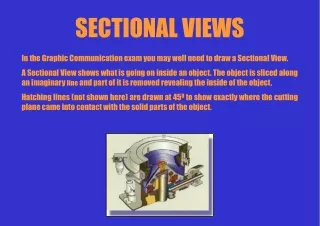
SECTIONAL VIEWS In the Graphic Communication exam you may well need to draw a Sectional View. A Sectional View shows what is going on inside an object. The object is sliced along an imaginary line and part of it is removed revealing the inside of the object. Hatching lines (not shown here) are drawn at 450 to show exactly where the cutting plane came into contact with the solid parts of the object.
1 ENGINEERING SUPPORT BLOCK Q1 Drawing a SECTIONAL View to show information more clearly can be very helpful. Sometimes the ELEVATION, END ELEVATION and PLAN combined still do not tell the whole story of what is going on with an object. Perhaps the most interesting detail is happening inside the object. In this situation, a SECTIONAL drawing is used. In a SECTION, we imagine what would happen if we sliced the object along an imaginary line and removed part of the object. When we draw what is left, the finished drawing often gives a much clearer picture of what is going on. There are lots of rules to remember when SECTIONING and we will learn them gradually. X Here are a couple of PICTORIAL views of a simple engineering block. The cutting plane is clearly marked X-X. X X PICTORIAL VIEWS X CUTTING PLANE Look at the two ORTHOGRAPHIC views of the block. You are asked to complete the SECTIONAL view X-X. HERE ARE SOME IMPORTANT RULES . . . • the cutting plane X-X defines where the object is to be split • surfaces touched by the cutting plane should be hatched with 450 lines • certain types of items are NEVER hatched. (you will find out which) • the arrows point at the bit that is left • DO NOT include hidden detail in a sectional drawing PLAN X HATCHING LINES PLAN CUTTING PLANE LINE X X SECTION X-X ELEVATION X ELEVATION SECTION X-X
X X 2 Q2A SUPPORT BLOCK SUPPORT BLOCK Q2B Here are a couple of PICTORIAL views of a simple engineering block. In the first view the block has been halved and in the second view the block is complete. The cutting plane is clearly marked X-X. Here are a couple of PICTORIAL views of a simple engineering block. In the first view the block has been halved and in the second view the block is complete. The cutting plane is clearly marked X-X. X X This block would be used to support the weight of a square bar. The largest flat square face would be secured to a surface and the square bar would fit in the square hole, thus giving it support. Here are two PICTORIAL views of a simple block which would be used to support the weight of a round bar. The flat square face would be secured to a surface and the round bar would fit in the round hole, thus giving it support. Take a look at the two ORTHOGRAPHIC views of the block. You are asked to complete the SECTIONAL view X-X. Take a look at the two ORTHOGRAPHIC views of the block. You are asked to complete the SECTIONAL view X-X. PLAN X PLAN X X X SECTION X-X ELEVATION ELEVATION SECTION X-X
Sectioned metal tube 3 Q3A Q3B METAL TUBING SUPPORT BLOCK Metal tubing is used for all sorts of purposes in engineering. Most commonly it is used as pipework to carry a wide range of liquids and gases. It can also be used to construct frameworks to support all kinds of furniture etc. and in the making of bicycles. This small block has been manufactured to strengthen a larger framework. It was found that the large framework was much too flimsy and required to be made more rigid. Small support pieces like the one shown here were fitted to all of the joints to add rigidity. One of the blocks is shown here sectioned. Take a look at the two ORTHOGRAPHIC views of the tube shown below. You are asked to complete the SECTIONAL view Z-Z. Take a look at the two ORTHOGRAPHIC views of the block shown below. You are asked to complete the SECTIONAL view A-A. PLAN PLAN Z A A Z SECTION A-A ELEVATION ELEVATION SECTION Z-Z
4 Q4A ROLLER PULLEY WHEEL Q4B This plastic roller is used to allow heavy objects to be moved around. Four of these rollers placed at the corner of a flat board making an ideal transportation device for bulky items. The rollers become wheels when a rod is placed through a hole in the centre allowing the roller to spin around it. This pulley wheel is used as part of a lifting device to handle heavy objects. The lifting rope runs in the groove in the middle of the wheel and the wheel spins around a rod which runs through the hole in the centre. Take a look at the two ORTHOGRAPHIC views of the pulley wheel shown below. You are asked to complete the SECTIONAL view D-D. Take a look at the two ORTHOGRAPHIC views of the roller shown below. You are asked to complete the SECTIONAL view P-P. PLAN PLAN P D D P ELEVATION SECTION D-D ELEVATION SECTION P-P
X Y Y X 5 Q5 WALL BRACKET Here are a couple of PICTORIAL views of the wall bracket. The first view shows the complete bracket and the second shows the sectioned bracket. The general name for a device which is used to hang things on a wall is a BRACKET. Brackets come in all shapes and sizes. The one shown here is fixed to the wall by a screw which runs through the hole in the back of the bracket. Two prongs then stick out from the wall to support whatever is required. Take a look at the two ORTHOGRAPHIC views of the bracket shown below. You are asked to complete the SECTIONAL view X-X and then Y-Y. SECTION Y-Y X Y Y SECTION X-X ELEVATION END ELEVATION X
6 Q6 WOODEN TOY Here are a couple of PICTORIAL views of the wall bracket. The first view shows the complete bracket and the second shows the sectioned bracket. The general name for a device which is used to hang things on a wall is a BRACKET. Brackets come in all shapes and sizes. The one shown here is fixed to the wall by a screw which runs through the hole in the back of the bracket. Two prongs then stick out from the wall to support whatever is required. Take a look at the two ORTHOGRAPHIC views of the bracket shown below. You are asked to complete the SECTIONAL view X-X and then Y-Y. SECTION X-X
dia 60 dia 40 dia 16 Y 20 90 80 45 Y EXPLODED VIEW OF SWIVEL HOUSING AND PIVOT PIN 7 EXPLODED & ASSEMBLED VIEWS Q7 An exploded view of a salt dish is shown. You are also shown an ELEVATION and a PLAN of the salt dish with the lid in place. The weather vane shown here is an assembly of three parts ; the pointer, the swivel housing and the pivot pin. The PICTORIAL view shows how they all fit together. Take a look at how the weather vane fits together. Below is an exploded view of the swivel housing and the pivot pin. Use all of this information to complete the ASSEMBLED SECTION Y-Y. PLAN X X ASSEMBLED SECTION Y-Y SECTION X-X ELEVATION
8 A car heater control switch is shown here in various ways ; Photograph, PICTORIAL views and SECTIONS. The switch is an assembly of two parts. Exactly how they fit together is detailed in the SECTIONS. Q8 DASHBOARD HEATER CONTROL You are asked to complete the ELEVATION and then SECTIONB-B. SECTION B-B Audi TT Dashboard A B A 18 B B B A SECTION A-A ELEVATION A
back to menu ASSEMBLED VIEW 9 Q9 SPARKPLUG CONNECTOR Most garden lawn mowers are powered by electricity. Larger machines, designed for use in larger areas such as sports fields, parks etc. are more often powered by petrol engines. A petrol engine works by creating a series of small explosions, ignited by a device called a sparkplug. Here is how a sparkplug is put together . . . You are asked to complete the ASSEMBLED VIEW of the sparkplug. ELECTRODE CERAMIC INSULATOR SCREW ADAPTOR