Sectional Views
Sectional Views. Section Views. Section Views. Often there is a need to show interiors that cannot be illustrated clearly by hidden lines. Interiors are shown by slicing through the object resulting in a cutaway view of the part.

Sectional Views
E N D
Presentation Transcript
Sectional Views Section Views
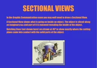
Section Views Often there is a need to show interiors that cannot be illustrated clearly by hidden lines. Interiors are shown by slicing through the object resulting in a cutaway view of the part. Cutaway views are called sectional views, cross sections, or simply sections.
Section Views The object Conventional hidden line technique Many times the interior of an object is so complicated that it is impossible or very difficult to represent that interior with conventional hidden lines. This often causes confusion in reading and interpreting the drawing. Therefore, sectioning is required in these cases.
Section Views Section technique The object cut Sectioning is a technique by which the object is sliced and the cutaway view of the part is then drawn. To show the construction clearly in many hollow objects, the front part is imagined to be removed to reveal the interior surface. Where and when this occurs the edges are represented with solid lines and the cut surface is crosshatched or section lined. The interior detail is now shown more clearly because the hidden lines have been replaced with visible object lines.
Section Views Visualizing a section view Given the object The top view and front view are shown as a typical orthographic projections with hidden lines.
Section Views Visualizing a section view A cutting plane is passed through the object, cutting the object.
Section Views Visualizing a section view The interior detail is now exposed and will appear as visible object lines To clarify the section view even further, the surfaces touched by the cutting plane are colored to distinguish between solid material and air space.
Section Views Visualizing a section view A cutting-plane line is used to indicate where the section is being cut. The arrow indicate the direction of sight. Crosshatching or section lining is applied to the surfaces that are in actual contact with the cutting plane.
Section Views To produce a section view a cutting plane is passed through the part (figure a). The cutting plane is removed and the two halves are drawn apart (figure b) exposing the interior detail.
Section Views A section view obtained by passing the cutting plane fully through the object is called a full section. In the front view the cutting plane appears as a line called a cutting-plane line. The arrows at the ends of the cutting-plane line indicate the direction of sight for the section view. To obtain the section view the right half of the front view is only imagined to be removed. The cross-hatched areas of the section view are those portions that are in actual contact with the cutting plane.
Section Views A correct front view and section view are shown in figure (a) and figure (b). All visible edges and contours behind the cutting plane should be shown. Section views are used primarily to replace hidden lines so as a rule hidden lines should be omitted in section views (figure d). A section-lined area is always completely bounded by a visible outline, never by a hidden line as in figure (e). Section lines in a section view must be parallel and at the same angle and direction (figure f).
Section Views Sectioning lining symbols can be used to indicate specific materials. These symbols represent general material types. Because there are so many different types of materials the general purpose cast iron symbol can be used for all materials.
Section Views The correct method of drawing section lines is shown in figure (a). Section lines are drawn thin and at an angle of 45 degrees unless there is some advantage in using a different angle. Section lines are spaced evenly approximately 1/16” to 1/8” or more depending on the sectioned area. As a rule, are spaced generously as possible and yet close enough to distinguish clearly the sectioned area.
Section Views If section lines drawn at 45 degrees would result in being parallel or perpendicular to a visible object line the angle should be changed to 30 degrees, 60 degrees, or some other angle.
Section Views The cutting plane is indicated in a view adjacent to the sectional view. In this view the cutting plane appears edgewise as a line called a cutting-plane line.
Section Views There are two styles of cutting-plane lines. The cutting-plane line in figure (a) is composed of equal dashes approximately 1/4” long with arrowheads indicating the direction of sight. For CAD drawings use the line type HIDDEN. The cutting-plane line in figure (b) is composed of alternate long dashes and pairs of short dashes plus arrowheads indicating the direction of sight. For CAD drawings use the line type PHANTOM2. Cutting-plane lines are drawn as thick as a visible object line or thicker. For CAD drawings set the line weight to either 0.020 or 0.030.
Section Views Correct and incorrect relations between cutting-plane lines and corresponding section views.
Section Views Visualizing a Section: Two views of an object to be sectioned are shown (figure a). It has a drilled and counterbored hole. The cutting plane is assumed to pass through the horizontal center line in the top view. The corresponding section view shown in figure (c) is incomplete because certain visible lines are missing. If the section view is viewed in the direction of sight shown in figure (b) the arcs A,B,C and D will be visible and appear as straight lines as shown in figure (d).
Section Views Half Sections: If a cutting plane passes halfway through an object the result is a half section (figure a). The half section has the advantage of showing the interior of one half of the object and the exterior of the other half (figure b). Note the cutting-plane line. Only one arrowhead is used to show the direction of sight. Hidden lines should be omitted from both halves of a half section view. A center line is used to separate the halves of the half section view.
Section Views Broken-Out Sections: Often only a partial section of a view is needed to expose interior shapes. Such a section, limited by an irregular break line is called a broken-out section.
Section Views Revolved Sections: The shape of a cross section of an object may be shown in the longitudinal view by means of a revolved section. Revolved sections are made by assuming a plane perpendicular to the center line or axis of the object and then revolving the plane 90 degrees about a center line at right angles to the axis.
Section Views Removed Sections: A removed section is a section view that is not in direct projection from the view containing the cutting plane. Removed sections should be labeled Section A-A and Section B-B, corresponding to the letters at the ends of the cutting-plane line. Removed sections should be arranged in alphabetical order from left to right on the drawing sheet
Section Views Offset Sections: In sectioning through an irregular object it is often desirable to show features that do not lie in a straight line by offsetting or bending the cutting plane. Such a section is called an offset section. The offsets or bends in the cutting plane are all 90 degrees and are never shown in the section view.
Section Views Ribs in Sections: To avoid a false impression of thickness and solidity, ribs, webs, gear teeth, and other similar flat features are not section lined even though the cutting plane passes through the feature. In the example the cutting plane A-A passes through the vertical rib or web but the rib or web is not section lined (figure a). Figure (b) is incorrect because it gives a false impression of thickness or solidity.
Section Views Aligned Sections: To include in a section view certain angled elements, the cutting plane may be bent to pass through those features. The plane and features are imagined to be revolved into the original plane. In the example the cutting plane is bent to pass through the angled arm and then revolved to a vertical position (aligned) from where it is projected across to the section view.