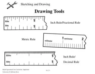
Mastering Dimensioning in Technical Drawing
Learn dimensioning techniques in technical drawing through linear, radial, angular, ordinate dimensions, and editing tools. Explore command sequences for precise annotations.

Mastering Dimensioning in Technical Drawing
E N D
Presentation Transcript
Technical Drawing – Week 4 2008-Fall
Dimensioning • Command Promt • Dimension Menu • Dimension Toolbox
Linear Dimensions • Command Sequence • Command: DIMLINEAR • First extension line origin or press ENTER to select: (pick P1) • Second extension line origin: (pick P2) • Dimension line location (Mtext/Text/Angle/Horizontal/Vertical/Rotated): (pick a point to position the dimension line, you will see the dimension rubber banding) • Command Sequence • Command: DIMLINEAR • First extension line origin or press ENTER to select: (press ENTER) • Select object to dimension:
Linear Dimensions • Command Sequence • Command: DIMCONTINUE • Specify a second extension line origin or (Undo/<Select>): (pick P3) • Specify a second extension line origin or (Undo/<Select>): (pick another or to end)
Linear Dimensions • Command Sequence • Command: DIMBASELINE • Specify a second extension line origin or (Undo/<Select>): (pick next point) • Specify a second extension line origin or (Undo/<Select>): (pick another or to end) • Select base dimension: ( again to end)
Linear Dimensions • Command Sequence • Command: DIMALIGNED • First extension line origin or press ENTER to select:(pick P1) • Second extension line origin: (pick P2) • Dimension line location (Mtext/Text/Angle): (pick a point)
Changing the Text • Select the dimension • Type DDEDIT, or ModifyObjectTextEdit • <> refers for the dimension value
The Radial Dimension Commands • Command Sequence • Command: DIMDIAMETER • Select arc or circle: (pick the circumference P1) • Dimension line location (Mtext/Text/Angle): (move the cursor until you are happy with the text position and then pick to complete the sequence) • Command Sequence • Command: DIMRADIUS • Select arc or circle: (pick the circumference P2) • Dimension line location (Mtext/Text/Angle): (move the cursor until you are happy with the text position and then pick to complete the sequence) • You can use the Center Mark command to annotate a circle or an arc with a cross at the center. The illustration above shows a center mark added to a circle after a diameter has been drawn. • Command Sequence • Command: DIMCENTER • Select arc or circle: (Pick the circumference of a circle or arc)
Angular Dimensions • Command Sequence • Command: DIMANGULAR • Select arc, circle, line, or press ENTER: (pick a line) • Second line: (pick another line) • Dimension arc line location (Mtext/Text/Angle): (pick point)
Ordinate Dimensions • Command Sequence • Command: DIMORDINATE • Select feature: (pick the point to annotate) • Leader endpoint (Xdatum/Ydatum/Mtext/Text): (pick endpoint or use one of the options) Ordinate Default Ordinate Ydatum
Annotation with Leaders • Keyboard LEADER • The Leader command can be used to annotate any point on a drawing. The command sequence below was used to draw the leader shown in the illustration above. • Command Sequence • Command: LEADER • From point: (pick the point to annotate) • To point: (pick vertex point) • To point (Format/Annotation/Undo)<Annotation>: (pick end point) • To point (Format/Annotation/Undo)<Annotation>: • Annotation (or press ENTER for options): Corner of • MText: building • MText: (to end)
Editing Dimensions • The Dimension Text Edit Command • Pull-down DimensionAlign Textoptions • Keyboard DIMTEDIT • Command Sequence • Command: DIMTEDIT • Select dimension: (pick the dimension you want to edit) • Enter text location (Left/Right/Home/Angle): (pick a new position or use an option) • The results of the four available options are shown in the illustration below. • The Left option moves the text to a left justified position within the dimension. • The Right option moves the text to a right justified position within the dimension. • The Home option returns the text to the home position after it has been modified. • The Angle option enables the text to be rotated about its center.
Editing Dimensions • The Dimension Edit Command • Keyboard DIMEDIT • The Dimension Edit command can be used to modify and change the text of any number of dimensions. The command could, for example, be used to add a standard prefix or suffix to a number of dimensions. • Command Sequence • Command: DIMEDIT • Dimension Edit (Home/New/Rotate/Oblique) <Home>: (choose an option) • Select objects: (pick one or more dimensions) • Select objects: (pick more or end) • The command sequence will vary depending upon which option has been chosen but the results of the various options are illustrated below
Tips & Tricks • Always attempt to use the least number of dimensions in order to provide the maximum amount of information. • Avoid giving duplicate information. For example, if you use a number of running dimensions along the length of an object, it is not necessary to include an additional dimension for the whole length. In the illustration on the right the "50" dimension is unnecessary because it gives no extra information and simply duplicates that which can be inferred from the "20" and "30" dimensions. This will also avoid any ambiguity which may arise from inaccurate dimensioning. • Sometimes it may be more appropriate to add notes to your drawing which include dimension information rather than attempt to dimension small or complex items. • If you do not include any units information with your dimensions you must always add a note to your drawing such as "All dimensions are in millimeters" to make it absolutely clear
Exercise • Draw a regular Turkish Flag according to the law.
Exercise • Draw the site
Exercise • Hints • To get started, try drawing the first boundary line using a relative polar co-ordinate in the form, @450<60, where "450" is a distance and "60" is an angle. You will find lots of information about co-ordinates in the "Using Co-ordinates" tutorial. • The Offset command will be very useful when you are constructing the site boundary. You will find the Offset command on the Modify pull-down (ModifyOffset) and on the Modify toolbar . You will also find more information about the Offset command on the "Modifying Objects" tutorial. • The site boundary cannot accurately be drawn without the use of Osnaps such as Endpoint. Use the "Object Snap" tutorial to learn about using object snaps. • Make sure your drawing has a good layering structure. You can always use the Modify Properties command, to change the layer of objects after they have been drawn. You can start the Modify Properties command from the Modify pull-down, ModifyProperties or from the Object Properties toolbar. • Feel free to interpret the brief in any way you feel appropriate, however, you must also concentrate your efforts to produce a good-looking, illustrative plan. Since trees will be an important element of the design, spend some time developing some useful tree symbols. • Don't forget to save your drawing regularly.