Step One
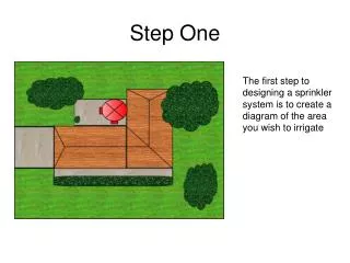
Step One. The first step to designing a sprinkler system is to create a diagram of the area you wish to irrigate. Step Two. Next the property is split into areas or zones. This is done because there is not enough water capacity to irrigate the entire property at once.

Step One
E N D
Presentation Transcript
Step One The first step to designing a sprinkler system is to create a diagram of the area you wish to irrigate
Step Two Next the property is split into areas or zones. This is done because there is not enough water capacity to irrigate the entire property at once. You want to try and create your zones roughly the same size. However, that is not always possible. This particular property is divided into 4 zones.
Step Three Once the property has been divided into zones, sprinkler head locations need to be determined (black circles, half circles and quarter circles). Sprinklers have spray patterns and spray diameters. Notice how all the circles overlap. This creates full water coverage for the area. (Bottom Diagram)
Sprinkler Patterns and CoverageAreas • Overlap coverage • Cutouts for spray coverage • Spray direction ¼ circle ½ circle Full circle
Step Four Now you will need to determine how you will layout your PVC Pipe to supply water to your sprinkler heads in each zone. The black lines on the diagram represent how the pipes will be run for each zone. The blue lines represent piping that connects each zone to the control valves and timer.