Ankle positioning and load device
Ankle positioning and load device. Faculty Advisors: Dr. Stacie Ringleb and Dr. Sebastian Bawab Vasile Grigorita Dominick Hudson Jin Hyuk Kim Bryan Mazac Christopher Parrish Christopher Villaire. 09/25/2013. Purpose.

Ankle positioning and load device
E N D
Presentation Transcript
APLD Ankle positioning and load device Faculty Advisors: Dr. Stacie Ringleb and Dr. Sebastian Bawab VasileGrigorita Dominick Hudson Jin Hyuk Kim Bryan Mazac Christopher Parrish Christopher Villaire 09/25/2013
APLD Purpose • The purpose of this project was to design a device capable of loading and positioning the ankle in the closed kinetic chain so that the dynamics of the ankle can be realistically analyzed • The device needed to be user-friendly and incorporate five DOF.
APLD Needs To be Addressed • By the end of the semester our prototype should be able to: • Move in both directions for each Degree of Freedom • Endure a realistic load representing average body weight • Enable accurate reading of foot placement by means of a tracking pad • Operate a reasonable number of cycles before maintenance is required • Be cost efficient and easily reproduced by a manufacturing plants
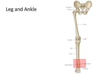
APLD Range of Motions • This device will be able to move the ankle in five ranges of motion. • Three ranges of motion are shown • The last two are translation in the X and Y plane.
APLD Previously Completed • The team created a preliminary device design that had the ability to support up to a 200 pound load on load cell. • Materials were sent to the Old Dominion University machine ship for fabrication. • Once all the parts were received the y-axis rotation joint was assembled. • A final design was put together with a working control algorithm.
APLD Scaled Model • A 3D print on a 1/3 scale of the final project was created .
APLD Expanding On Previous Work • The previous group created a design to account for the 5 Degrees of Freedom yet only made a physically working model testing 1 Degree being Plantar Flexion /Dorsiflexion • Our job was to modify their design to address design flaws. • Flaws that were identified • Too many unnecessary parts • Too much welding • Safety switch needed
APLD Modifications • Have made modifications to the blueprints to accommodate the actual parts that will be ordered • Have restructured some of the device to reduce the need for welding and to reduce the need for an abundance of parts. • Have started to modify the control algorithm to allow for other degrees of freedom.
APLD Outstanding • Need to purchase parts • Need to get parts manufactured by machine shop • Assembly • Test the control algorithm • Test the structural soundness of the device • Final Testing
APLD Gantt Chart