Ankle Positioning Device
Ankle Positioning Device. Faculty Advisors: Dr. Bawab & Dr. Ringleb Students: Vasile Grigorita , Dominick Hudson, Jin Hyuk Kim, Bryan Mazac , Christopher Parrish, and Christopher Villaire. Introduction. Ankle injuries are one of the most common injuries.

Ankle Positioning Device
E N D
Presentation Transcript
Ankle Positioning Device Faculty Advisors: Dr. Bawab & Dr. Ringleb Students: VasileGrigorita, Dominick Hudson, Jin Hyuk Kim, Bryan Mazac, Christopher Parrish, and Christopher Villaire
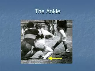
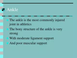
Introduction • Ankle injuries are one of the most common injuries. • 25,000 Ankle Injuries happen every day in America. • The ankle region consists of three joints which provide balance, strength, and stability.
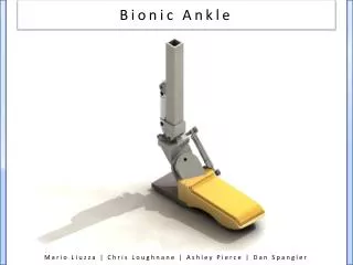
Purpose • To design a device capable of loading and positioning the ankle in a closed kinetic chain so that the dynamics of the ankle can be realistically analyzed.
Joint ranges of motion Plantarflexion/Dorsiflexion Abductor/Adductor Eversion/Inversion The other two motions are translations in the X and Y planes.
Product Features • Easy to use interface • Undergo realistic loading via load cell • Obtain accurate ankle motion analysis. • Minimal machining and cost efficient.
Control Methods • Accelerometer & Gyro • Arduino Software • Lab-View
- Definition • Laboratory Virtual Instrument Engineering Workbench • Asystem-design platform and development environment for a Visual Programming Language
Mechanical Design • Bearing Selection • Horizontal Translation • Side-mount track roller carriage and guide rails • 3 internal track rollers per carriage • Vertical Translation • Self-lubricated pillow block linear sleeve • Chemical-resistant PFTE (Polytetrafluoroethylene) liner • Machining • Alignment issues with initial design utilizing base plate welds • Warping • Making adjustments after fabrication • Solution • Redesign all base plate and alignment sensitive components • Utilize U-channels for transition tiers • Assemble components with threaded fasteners
Machining and Assembly • Replaced welds with cap screws. • Shimmed gap between pillow bearings and weight plate was added.
The Device Operation • Can be operated remotely or by keyboard inputs • Motion can be utilized in series or in parallel • Safety switches will prevent further injury
Outstanding Tasks • Add an adjustable clamp to the foot plate • Add a joystick or handheld motion sensor to control servos