The Network Layer
Explore the key issues of portability and scalability in the network layer, including the ability to connect different technologies and scale to the size of the Internet. Understand the purpose of the network layer, its important functions of routing and forwarding, and the service models for transporting packets. Discover the service abstractions and connection models, virtual circuit and datagram, and learn about virtual circuit switching and forwarding. Compare the advantages and disadvantages of virtual circuits and datagrams, and understand how packets are forwarded in datagram networks. Finally, delve into the graph-theoretic routing problem and the scalability challenges of centralization.

The Network Layer
E N D
Presentation Transcript
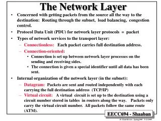
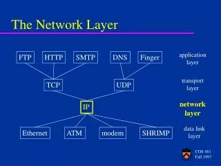
Given a packet, send it across the network to destination 2 key issues: Portability: connect different technologies Scalability To the Internet scale network data link physical network data link physical network data link physical network data link physical network data link physical network data link physical network data link physical network data link physical application transport network data link physical application transport network data link physical Purpose of Network layer
What does it involve? Two important functions: • routing: determine path from source to dest. • forwarding: move packets from router’s input to output T3 T1 T3 Sts-1 T1
Q: What service model for “channel” transporting packets from sender to receiver? guaranteed bandwidth? preservation of inter-packet timing (no jitter)? loss-free delivery? in-order delivery? congestion feedback to sender? Network service model The most important abstraction provided by network layer: ? ? virtual circuit or datagram? ? service abstraction Which things can be “faked” at the transport layer?
b b 1 1 B C B C A Two connection models • Connectionless (or “datagram”): • each packet contains enough information that routers can decide how to get it to its final destination • Connection-oriented (or “virtual circuit”) • first set up a connection between two nodes • label it (called a virtual circuit identifier (VCI)) • all packets carry label 1 A
used to setup, maintain teardown VC setup gives opportunity to reserve resources used in ATM, frame-relay, X.25 not used in today’s Internet application transport network data link physical application transport network data link physical Virtual circuits: signaling protocols 6. Receive data 5. Data flow begins 4. Call connected 3. Accept call 1. Initiate call 2. incoming call
2 1 5 1 2 2 1 a b c Virtual circuit switching • Forming a circuit: • send a connection request from A to B. Contains VCI + address of B • rule: VCI must be unique on the link its used on • switch creates an entry mapping input messages with VCI to output port • switch picks a new VCI unique between it and next switch
a b c Virtual circuit forwarding • For each VCI switch has a table which maps input link to output link and gives the new VCI to use • if a’s messages come into switch 1 on link 2 and go out on link 3 then the table will be: (Input link,VCI) (output link, new VCI) (1, 2) (?, ?) (1, 5) (?, ?) Switch 1 2 Switch 2 1 5 1 2 Switch 3 2 1
Virtual Circuits: Discussion • Plusses: easy to associate resources with VC • Easy to provide QoS guarantees (bandwidth, delay) • Very little state in packet • Minuses: • Not good in case of crashes • Requires explicit connect and teardown phases • What if teardown does not get to all routers? • What if one switch crashes? • Will have to teardown and rebuild route
no call setup at network layer routers: no state about end-to-end connections no network-level concept of “connection” packets typically routed using destination host ID packets between same source-dest pair may take different paths Best effort: data corruption, packet drops, route loops application transport network data link physical application transport network data link physical Datagram networks 1. Send data 2. Receive data
0 1 S1 0 1 S2 2 2 S3 1 0 d c b a Datagrams: Forwarding How does packet get to the destination? • switch creates a “forwarding table”, mapping destinations to output port (ignores input ports) • when a packet with a destination address in the table arrives, it pushes it out on the appropriate output port • when a packet with a destination address not in the table arrives, it must find out more routing information (next problem)
Datagrams • Plusses: • No round trip connection setup time • No explicit route teardown • No resource reservation each flow could get max bandwidth • Easily handles switch failures; routes around it • Minuses • Difficult to provide resource guarantees • Higher per packet overhead • Internet uses datagrams: IP (Internet Protocol)
Datagrams Forwarding • How to build forwarding tables? • Manually enter it • What if nodes crashed • What about scale? • The graph-theoretic routing problem • Given a graph, with vertices (switches), edges (links), and edge costs (cost of sending on that link) • Find the least cost path between any two nodes • Path cost = (cost of edges in path)
Simple Routing Algorithm • Choose a central node • All nodes send their (nbr, cost) information to this node • Central node uses info to learn entire topology of the network • It then computes shortest paths between all pairs of nodes • Using All Pair Shortest Path Algorithm • Sends the new matrix to every node • Nice, simple, elegant! • What is the problem? • Scalability: centralization hurts scalability • Central node is “crushed” with traffic
Link State Routing • Basic idea: • Every node propagates its (nbr, cost) information • This information at all nodes is enough to construct topology • Can use a graph algorithm to find the shortest routes • Mechanisms required: • Reliable flooding of link information • Method to calculate shortest route (Dijkstra’s algorithm) • Example link state update packet: • [node id, (nbr, cost) list, seq. no., ttl] • Seq. no. to identify latest updates, ttl specifies when to stop msg.
Reliable flooding receive(pkt) If already have a copy of LSP from pkt.ID if pkt’s sequence number <= copy’s discard pkt else decrement pkt.TTL replace copy with pkt forward pkt to all links besides the one that we received it on # done every 10 minutes or so gen_LSP() increment node’s sequence # by one recompute cost vector send created LSP to all neighbors
A A A A D D D D B B B B C C C C 2+e 2+e 0 0 1 1 1+e 1+e 0 e 0 0 Discussion: Link-State Routing • Plusses: • Simple, determines the optimal route most of the time • Used by OSPF • Minuses: • Might have oscillations • Avoid using load as cost metric, reduce herding effect 1 1+e 0 2+e 0 0 0 0 e 0 1 1+e 1 1 e … recompute … recompute Least loaded => Most loaded Initially start with almost equal routes … everyone goes with least loaded
Is our routing algo scalable? • Route table size grows with size of network • Because our address structure is flat! • Solution: have a hierarchical structure • Used by OSPF • Divide the network into areas, each area has unique number • Nodes carry their area number in the address 1.A, 2.B, etc. • Nodes know complete topology in their area • Area border routers (ABR) know how to get to any other area
Forwarding table for switch 1 Destination switch port 2. ? 3. ? 1.b ? 1.a ? S3 1.b 1.a 3.a 2.a 3.b 2.b Hierarchical Addressing Zone 2 0 1 S1 1 0 2 S2 2 3 1 0 2 Zone 3
0 net host 1 7 24 bits IP has 2-layer addressing • Each IP address is 32 bits • Network part: which network the host is on? • Host part: identifies the host. • All hosts on same network have the same network part • 3 classes of addresses: A, B and C 18.26.0.1 host network 32-bits 1 0 net host 110 net host 2 14 16 bits 3 21 8 bits
multicast address 1110 network host 110 network 10 host 32 bits IP addressing • The different classes: • Problems: inefficient, address space exhaustion class 1.0.0.0 to 127.255.255.255 A network 0 host 128.0.0.0 to 191.255.255.255 Unicast B 192.0.0.0 to 223.255.255.255 C 224.0.0.0 to 239.255.255.255 D Multicast 240.0.0.0 to 255.255.255.255 reserved E Reserved 1111
host part network part 11001000 0001011100010000 00000000 200.23.16.0/23 IP addressing: CIDR • Classless InterDomain Routing • network portion of address of arbitrary length • address format: a.b.c.d/x, where x is # bits in network portion • Examples: • Class A: /8 • Class B: /16 • Class C: /24
Internet Protocol Datagram IP protocol version Number 32 bits total datagram length (bytes) type of service head. len header length ver length for fragmentation/ reassembly fragment offset “type” of data flgs 16-bit identifier max number remaining hops (decremented at each router) upper layer time to live Internet checksum 32 bit source IP address 32 bit destination IP address upper layer protocol to deliver payload to E.g. timestamp, record route taken, pecify list of routers to visit. Options (if any) data (variable length, typically a TCP or UDP segment)
Datagram Portability • IP Goal: To create one logical network from multiple physical networks • All intermediate routers should understand IP • IP header information sufficient to carry the packet to destination • Goal: Run over anything! • Problem: • Physical networks have different MTUs • “max. transmission unit”: 1500 for Ethernet, 48 for ATM • Solution 1: • Fit everything in the MTU (!)
IP Fragmentation & Reassembly • Solution 2: (the one used) • If packet size > MTU of network, then fragment into pieces • Each fragment is less than MTU size • Each has IP headers + frag bit set + frag id + offset • Packets may get refragmented on the way to destination • Reassembly only done at the destination • What is a good initial packet size? reassembly fragmentation: in: one large datagram out: 3 smaller datagrams