Download
1 / 37
370 likes | 401 Vues
This study focuses on designing and fabricating Titanium Nitride (TiN) resonators for high-Quality Factor (Qi) applications. The impact of process techniques, materials, and interfaces on resonator performance is explored, highlighting TiN as a low-loss material with promising characteristics for quantum computing and photon detection.

E N D
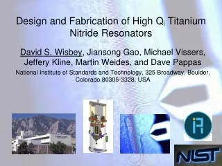
Design and Fabrication of High Qi Titanium Nitride Resonators David S. Wisbey, Jiansong Gao, Michael Vissers, Jeffery Kline, Martin Weides, and Dave Pappas National Institute of Standards and Technology, 325 Broadway, Boulder, Colorado 80305-3328, USA
CPW and Lumped Element TiN Resonators • Half wave coplanar waveguide (CPW) resonators and lumped element were fabricated using a low power SF6 etch • TiN was deposited on HF dipped Si(100) to eliminate loss at the interface David Wisbey, et al., J. Appl. Phys. 108 , 093918 2010
Internal Quality Factor is High For Resonators Made From TiN
Fitting Data for Half Wave TiN CPW Resonator Tc = 5.1 K • We perform high power fitting to get Qi • TiN was deposited on HF dipped Si(100) to eliminate loss at the interface J. Gao, et al. Appl. Phys. Lett. 92, 152505 (2008) H. Paik, et al., Phys. Lett. 96, 072505 (2008).
Increasing Trench Depth Decreased the Low Power Loss Removing the dielectric in the gap of the resonator decreased the loss and shifted the resonance frequency. Over etch depth
Internal Quality Factor is High For Resonators Made From TiN
X-Ray Diffraction of TiN as a Function of N2 Concentration Ti(200) Si(200) (deg) M. Vissers, et al., Appl. Phys. Lett. 2010 vol. 97 pp. 232509
Tc is Can Be Tuned by Varying the N2 Concentration During Deposition H. Leduc, Appl. Phys. Lett. 2010 vol. 97 pp. 102509
Conclusions: • Kinetic inductance and Tc of TiN films can be costume tailored to preferred values by changing the N2 concentration in the films • Lumped element TiN LC resonators are promising as single photon detector • As the stress decreases, the Tc also decreases • As the trench depth increases due to over etch the internal loss decreases
Fitting Data for Tc = 5.1 K Quantum Computing with Molecules N. Gershenfeld, I. L. Chuang, Sci. Amer. 278, 66 (1998).
Scanning Electron Microscope Images of the Different Processing Techniques CF4/O2 Nb Etch High Power SF6 Nb Etch Low Power SF6 Nb Etch
A Microwave in a Resonator Acts Like a Laser Bouncing Between two Mirrors
Different Types of Microwave Resonators • Multiplexed resonators have an advantage because if one fails, it is still possible to measure other devices. • 1/2 wave single resonators disadvantageous because if failure occurs, additional cool down is required.
Adiabatic Demagnetization Refrigerator • Demonstrated T < 100 mK • 1 day turnaround
Superconducting Microwave Resonators to Study Loss • Absorption: • e.g. Nb on Si • Q=267k • Loss =1/Q • ~7x10⁻⁶ • Test: • Superconductors – Nb, Al • Re, TiN – reduced oxidation • Substrates – Si, sapphire • SiOX, AlOX, SiN, a-Si
Rhenium After Exposure to Atmosphere 10 µm Gimpl et al., Trans. Metallurg. Soc. AIME 236, 331 (1966).
Annealing Rhenium Changes the Type of Surface Oxide Formed • Spots cover surface: ~100 µm diameter & 1.3 µm tall. • Cannot remove with Acetone, IPA, or water • Chemical reaction • Whiskers: ~100 µm long & 0.3 µm tall • AES: Re, C, & O • Can rinse away with Acetone, IPA, or water
Single photon loss measurements in microwave resonators T1 5 - 30 μs 0.04 - 1 μs 1/26/11
Difference Between Low and High Power Loss is Due to Materials
Loss can by Caused by Polar Impurities Schickfus et. al found that loss originated from polar impurities such as OH-, F-, orCl- in the insulating material. Temperature and intensity dependence of the dielectric absorption of vitreous silica at 10 GHz. The dashed line indicates the contribution of the relaxation process. [Von Schickfus, Phys. Lett. 64A, 144 (1977)]
Processing Affects the Loss (1/Q) Rrms= 45.0 nm • HF dipped resonators have less impurities between metal and substrate and have lower loss • Surface roughness and loss not always correlated Rrms= 0.8 nm Rrms= 11.0 nm Rrms= 10.8 nm
1/Qi=tanδi Loss (1/Q) of Different Metals
Summary of Findings • Overall loss is affected by the surface roughness, but loss from materials is independent of surface roughness • Improving the material by eliminating defects and impurities decreases loss • Oxide at the interface between the superconducting metal and the dielectric substrate greatly increases the loss • Titanium nitride is a very low loss material and is promising candidate for qubits • Low temperature boron carbide (B4C) has less loss due to materials than amorphous silicone oxide (SiOx)
Future Plans: • Find new materials that allow quantum states to be stored longer • New materials should be grown and tested as solid state devices • Purposefully induce defects and add impurities to study the effect • New possible materials include boron carbide (B4C) and boron nitride (BN) • Study the electronic structure of the superconductor dielectric interface
Using HF Clean Significantly Reduces Loss in Rsonators Fr vs. T • Gap roughness does not significantly reduce TLS loss • Careful substrate preparation interface between Nb and Si reduces TLS loss • This means TLS reside primarily at the metal/substrate interface
Loss Tangent as a Function of Processing Surface roughness in the gap of CPW does not affect the loss due to TLS CF4/O2 Nb Etch High Power SF6 Nb Etch
Resonance Frequency vs. Temperature For B4C and SiOx df0/f0 1/Q=1.93*10-4 1/Q=1.3*10-4 • Reasons for B4C: • Strong intericosahedral bonding and • Weak polarizability • B4C is extremely physically hard • Easy to grow using sputter deposition 1/Q=8.6*10-6 1/Q= 3.2*10-4 df0/f0 1/Q= 1.7*10-4 Temperature (K)
Microwave Modeling Software is Used to Design Resonant Cavities Lc A= 4.01×10⁻⁶ GHz-1 µm-1 B= -3.35×10⁻⁸ µm-1 C= 2.60×10⁻⁵ GHz-1 D= 4.55 ×10⁻⁸.
The Quantum Computing Challenge Coupling Isolation Systems: Superconductors Phase, charge, flux ~~~~~~~~~~ Semiconductor spin Quantum dot ~~~~~~~~~ NMR Neutral atoms Ions Photons • Initialize single photons • Interact • Readout
Quantum Computing with Trapped Ions at NIST • 9Be+ ions in RF traps • Addressed with focused lasers • Ions are moved into 150 zones • Long coherence times ~ seconds • Challenges • ion heating from fluctuations on surfaces • Two level charge systems
What Are CPW Resonant Cavities Used for in the Context of Quantum Information Processing? • CPW resonant cavities are superconducting LC circuits used to store single photons • CPWs act as quantum information buses between qubits. • A simpler tool to measure loss in supercondcuting circuits than a qubit in terms of fabrication and measurement • If a squid loop is added, could be used as a qubit also
Resonator Q measurement • Fit each peak for: • Qr – observed resonance Q • QC – feedline-resonator coupling • fr – resonance frequency Get Qi => internal quality factor from: Lossresonance = Losscoupling + Lossinternal 6 *
Where are Two Level Systems Located? Gao and colleagues showed the observed loss in their multiplexed CPW corresponds to Fδ=3*105 for a 3µm resonator which is consistent with a ~2nm layer of TLS loaded material on the metal surface or ~3nm layer on the gap surface J. Gao, et. al, Appl. Phys. Lett. 92, 152505 (2008)