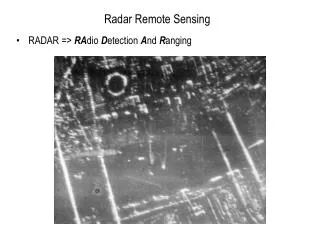
Radar Imaging with Compressed Sensing
Radar Imaging with Compressed Sensing. Yang Lu April 2014 Imperial College London. Outline. Introduction to Synthetic Aperture Radar (SAR) Background of Compressed Sensing Reconstruct Radar Image by CS methods. Introduction to SAR . Important elements of SAR

Radar Imaging with Compressed Sensing
E N D
Presentation Transcript
Radar Imaging with Compressed Sensing Yang Lu April2014 Imperial College London
Outline • Introduction to Synthetic Aperture Radar (SAR) • Background of Compressed Sensing • Reconstruct Radar Image by CS methods
Introduction to SAR Important elements of SAR • Range Resolution and Azimuth Resolution • Chirp signal and Matched Filter
Range Resolution and Azimuth Resolution of SAR http://www.radartutorial.eu/
Range Resolution 1 • Pulse signal (constant frequency signal)
Range Resolution 2 • The resolution related with pulse width ( slant range resolution) : pulse width c : speed of pulse 2 : that is a round trip
Range Resolution 3 • If the incident angle is • Then the ground range resolution will be
Azimuth Resolution 1 • Assume two points with same range Can’t distinguish A from B if they are in the radar beam at the same time
Azimuth Resolution 2 • The azimuth resolution defined by : R: the slant range : the wavelength L: the length of antenna
LFM Signal • Linear Frequency Modulated Signal (Chirp Signal) Where t: a time variable (fast time) T: duration of the signal K:is the chirp rate So the bandwidth of the signal is:
Matched Filter • The output of the a Matched Filter is: : the received signal and means convolution : the duplicated signal of the original signal and means complex conjugate
Matched Filter (example) • If After delay, we receive the signal The reference signal will be
Matched Filter (example) • Output signal of the matched filter So 3dB width of the main lobe
Range resolution improved • The range resolution improved Now we can distinguish B from C
Range resolution improved Original ground range resolution: Now replace with 3dB main lobe width= Finally, the improved ground range resolution will be :
Phase difference : phase difference between the transmitted and the received signal : the distance (round trip) : the wavelength of the transmitted signal http://www.radartutorial.eu/
SAR Azimuth Resolution • The phase change of the radar signal will be By Pythagorean theorem : a time variable (slow time) :the speed of plane Synthetic Aperture Radar Polarimetry (J.V. Zyl and Y. Kim)
SAR Azimuth Resolution Substitute The instantaneous frequency change of this signal is Which also can be considered as LFM signal And the total time
SAR Azimuth Resolution The The time resolution will be So the azimuth resolution (in distance) will be
2D signal of the target • One target have two equations-one is in the range direction (variable: fast time t) and another is in the azimuth direction (variable :slow time) • If consider the signal on the two direction simultaneously, that will be a 2-dimensional signal with variable t and .
2D signal of the target : a complex constant : the centre frequency (carrier frequency) Signal Energy
2D signal space • The received signals are stored in the signal space Digital Processing of Synthetic Aperture Radar Data: Algorithms and Implementation ( G.Cumming and H.Wong)
SAR impulse response • If we ignore the constant of , we get the impulse response of SAR sensor: The received signal of the ground model can be built as the convolution of the ground reflectivity with the SAR impulse response (with additive white noise):
Radar Image Radar algorithms are trying to obtain the ground reflectivity function based on the received radar signal. • Traditional methods Range-Doppler Algorithm Chirp scaling algorithm Omega-K algorithms
Background of Compressed Sensing Assume an N-dimensional signal has a K-sparse representation () in the basis If we have a measurement matrix () to measure and encode the linear projection of the signal we get measurements If , there will be enormous possible solutions. And we want the sparsest one.
Compressed Sensing • CS theory tells us that when the matrix A= has the Restricted Isometry Property (RIP), then it is indeed possible to recover the K-sparse signal from a set of measurement But RIP condition is hard to check. An alternative way is to measure the mutual coherence denotes the column of matrix A Compressive Radar Imaging (R. Baraniuk and P.Steeghs)
Compressed Sensing • We want to be small (incoherence) CS theory has shown that many random measurement matrices are universal in the sense that they are incoherent with any fixed basis with high probability Compressive Radar Imaging (R. Baraniuk and P.Steeghs)
Reconstruct Radar Image by CS methods • When RIP/incoherency holds, the signal can be recovered exactly from by solving an minimization problem as:
Reconstruct Radar Image by CS methods • If the measurement matrix is a causal, quasi-Toeplitz matrix , the results also show good performance. (Right shift distance=
Causal, quasi-Toeplitz Matrix (Example) If M=4, N=8 then right shift distance D= is the element of a pseudo-random sequence
Causal, quasi-Toeplitz Matrix The measurements of the signal will be
CS-based Radar We already know For simplicity, just consider 1D range imaging model and ignore the noise Under this condition, can be considered as the transmitted radar pulse is the time delay. A is the attenuation.
CS-based Radar Assume, the target reflectivity function is k-sparse in some basis. The PN or Chirp signals transmitted as radar waveforms (t) form a dictionary that is incoherent with the time, frequency and time-frequency bases.
CS-based Radar • Let the transmitted radar signal be the PN signal • The target reflectivity generated from N Nyquist-rate samples n=1,…,N via where • The PN signal generated from a N-length Bernoulli vector via
CS-based Radar The received signal will be And we sample it every second
CS-based Radar (Results) The target reflectivity function can be recovered by using an OMP greedy algorithm y Compressive Radar Imaging (R. Baraniuk and P.Steeghs)
Another Example (2-dimensional) The 2D received signal of a point target If ignore the antenna pattern =1, be a constant which is the radar cross section of point target
Another Example (2-dimensional) The approximate received signal will be For a measurement scene () , the recorded echo signal will be : samples on the azimuth direction (slow time samples) : samples on the range direction (fast time samples) i: the point target in the scene
Discrete format of the scene where =
Discrete format of the scene :is additive white noise complete measurement matrix of SAR echo signal According to CS theory, we only need a small set of to successfully recover the sparse signal with high probability. Randomly select rows of matrix A by using random selection matrix
Discrete format of the scene We assume that have a sparse representationin a certain basis(for example, a set of K point targets corresponds to a sparse sum of delta functions as in , then we have Where =
, andare complex So we have We define signal, and as , ,
Final Format Sparest solution can be solved by norm minimization
ERS Ship Image Results SNR=20dB Noise free SNR=10dB RD algorithm d CS algorithm CS algorithm
Reference • R. Baraniuk and P. Steeghs.Compressive Radar Imaging. IEEE Radar Conference, April 2007. • S.J. Wei, X.L. Zhang, J.Shi and G.Xiang. Sparse Reconstruction For SAR Imaging Based On Compressed Sensing. Progress In Electromagnetics Research, P63-81, 2010. • J.V. Zyl and Y. Kim. Synthetic Aperture Radar Polarimetry. Dec 2010. • G. Cumming and H. Wong. Digital Processing of Synthetic Aperture Radar Data: Algorithms and Implementation. Dec 2007. • Radar Basics available at http://www.radartutorial.eu/index.en.html#this • Y.K. Chan and V.C. Koo. An Introduction to Synthetic Aperture Radar (SAR). Progress In Electromagnetics Research. P27-60, 2008.