Coordinate Systems in Geodesy
Coordinate Systems in Geodesy. By K.V.Ramana Murty, O. S. Contents:. What is Geodesy? Coordinate system in Geodesy Geocentric Cartesian Coordinate System Geodetic Coordinate System Topocentric Cartesian or local Geodetic Cartesian Coordinate System Planimetric Cartesian Coordinates System

Coordinate Systems in Geodesy
E N D
Presentation Transcript
Coordinate Systems in Geodesy By K.V.Ramana Murty, O. S.
Contents: • What is Geodesy? • Coordinate system in Geodesy • Geocentric Cartesian Coordinate System • Geodetic Coordinate System • Topocentric Cartesian or local Geodetic Cartesian Coordinate System • Planimetric Cartesian CoordinatesSystem • UTM • LCC
What is Geodesy ? • Geodesyis the science concerned with the exact positioning of points on the surface of the earth. • It also involves • The study of variations of the earth’s gravity • The study of the exact size and shape of the earth.
N N INDIA CG Geoid Best Fitting Local ellipsoid and Geocentric Ellipsoid
Geocentric & Locally Best Fitting Ellipsoids Ye Zw Ze Geoid Yw Globally Fitting Ellipsoid CG Locally Best Fitting Ellipsoid Translations - x, y, z Rotations - x, y, z Scale - s Xw Xe P(X,Y,Z) (,,h)
BENCH MARK HEIGHT OF BENCH MARK ABOVE MEAN SEA LEVEL HIGH WATER WAVE MEAN SEA LEVEL LOW WATER HEIGHT OF BENCH MARK ABOVE TIDEPOLE ZERO TIDE POLE ZERO NEW GENERATION WATER LEVEL MEASUREMENT SYSTEM
FLOAT TYPE TIDE GAUGE PRESSURE SENSOR TIDE GAUGE BEDPLATE BENCH MARK HEIGHT OF BED PLATE ABOVE ZERO OF TIDE GAUGE HEIGHT OF BENCH MARK ABOVE MEAN SEA LEVEL HEIGHT OF BENCH MARK ABOVE TIDE GAUGE ZERO HIGH WATER WAVE MEAN SEA LEVEL LOW WATER ZERO OF PRESSURE SENSOR STILLING WELL NEW GENERATION WATER LEVEL MEASUREMENT SYSTEM
Coordinate System • The coordinates of the points on the surface of the earth are required for performing survey operations. • These points are known as control points or stations • The coordinates of these points are determined with respect to certain coordinate systems. • The coordinate systems are defined by its axes and origin .
Coordinate System in Geodesy • There are four coordinate systems generally used in geodesy. • Geocentric Cartesian Coordinate System • Geodetic Coordinate System • Topocentric Cartesian or local Geodetic Cartesian Coordinate System • Planimetric Cartesian CoordinatesSystem
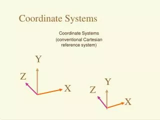
Geocentric Cartesian Coordinate System • The geocentric Cartesian Coordinate system is often called Earth Centered, Earth fixed (ECEF) or Conventional Terrestrial Reference System (CTRS). • This system is defined as: • Origin of coordinate system is placed at the centre of earth • Z axis aligned to the axis of rotation of earth which has the direction of the conventional International origin for polar motion (CIO). • The X axis passes through the intersection of primary plane (equatorial plane) and plane containing the Greenwich meridian • The systems are right handed.
Geocentric Cartesian Coordinate System • This system is suitable for mathematical calculations. • The coordinates do not give any indication that where the point is on the surface of the earth? • For example the coordinates of STITOP are X = 1208107.3807m Lat. 17 24 12.28N Y = 5967336.0758m Long. 78 33 17.87E Z = 1895612.6425m EHeight 433m
Geodetic Coordinate System • Geodetic Coordinate are: • Geodetic Latitude • Geodetic Longitude • Ellipsoidal Height. • Geodetic latitude () of a point on the surface of the earth is the angle between ellipsoidal normal passing through the point and equatorial plane, positive to north.
Geodetic Coordinate System (Contd.) • Geodetic Longitude () is the angle between the prime meridian (Greenwich meridian) and the meridian plane passing through the point (observer’s meridian), positive to the east. • Ellipsoidal height (h) of a point on the surface of the earth is the distance measured from the ellipsoid to the point along ellipsoidal normal passing through the point.
Representation of Latitude, Longitude and Ellipsoidal Height
EGM96: Geoidal Separation Values (N):The 15 x15 global geoid undulations produced by EGM96 The undulations range from -107 m to 85 m.
Conversion from Geodetic to Geocentric Where is given by
Topocentric Cartesian or Local Geodetic Coordinate System • The local geodetic coordinate system is defined as under • The origin is chosen along the ellipsoidal normal passing through observation station . • In practice it is at the observation station, on the ellipsoid. • The Z axis is the ellipsoidal normal. • The primary plane is the plane containing the origin and perpendicular to the Z axis. • Y axis is oriented along the meridian passing through origin positive to North. • X axis is oriented along the parallel passing through origin positive to east.
Topocentric Cartesian or Local Geodetic Coordinate System Ellipsoidal Normal
Topocentric Cartesian or Local Geodetic Coordinate System Coordinates of P w. r. t. ECEF P Coordinates of P w. r. t. ENU Ellipsoidal Normal Coordinates of origin w. r. t. ECEF Geographic Coordinates of origin
Relation Between ECEF and ENU (ECEF ENU) (ENU ECEF)
Planimetric Cartesian Coordinates (UTM, Lambert grid) • Planimetric Cartesian Coordinates are often called easting and northing. • They are the result of a cartographic projection from three dimensional geodetic coordinate(, ) into a two dimensional Cartesian space (x, y) on a map. • In this work, projected easting is denoted by x and northing by y.
Universal Transverse Mercator Projection (UTM) • The need of uniform Grid system was felt during 2nd World War. • UTM was developed after 2nd World War. • The Meridian and parallel are projected on Cylinder. • Calculation of distances and angles easier than from Geographical coordinates.
Organization of UTM Grid Zones • Although it is called the Universal Transverse Mercator Grid System, it does not cover the whole world. • The area covered by the system is the whole extent of Longitude and 80 degrees South Latitude to 84 degrees North Latitude. • Originally, the coverage of the UTM Grid System was from 80 degrees S to 80 degrees N. • On the request of Norway, it was extended Northwards 4 degrees.
Lambert Grid: • In Lambert Grids the meridian and parallels are projected on cone. • The extent is India and adjacent countries. • There are 9 Grid Zones covering India and Adjacent countries. • The North-South extent of each grid zone is limited to 8 and the E-W extent is limited to 16 • Hyderabad falls in Grid IIIA • Origin of Grid III A is Lat. 19 and Long. 80 • The coordinates assumed at origin are: • E = 2743196.4m • N = 914398.8m