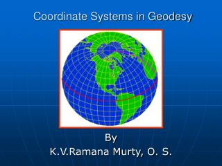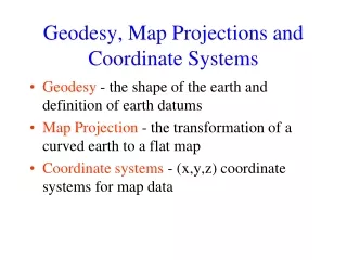
COORDINATE SYSTEMS IN GEODESY
Doç.Dr . Ersoy ARSLAN. COORDINATE SYSTEMS IN GEODESY. 1- INTRODUCTION

COORDINATE SYSTEMS IN GEODESY
E N D
Presentation Transcript
Doç.Dr. ErsoyARSLAN COORDINATE SYSTEMS IN GEODESY
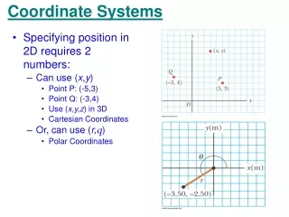
1- INTRODUCTION These notes discuss the precise definitions of, and transformations between, the coordinate systems to which coordinates of stations on or above the surface of the earth are referred. To define a coordinate system we must specify: • a) the location of the origin, • b) the orientation of the three axes, • c) the parameters (Cartesian, curvilinear) which define the position of a point referred to the coordinate system.
The earth has two different periodic motions in space. It rotates about its axis, and it revolves about the sun (see Figure 1-1). There is also one natural satellite (the moon) and many artificial satellites, which have a third periodic motion in space: orbital motion about the earth. These periodic motions are fundamental to the definition of systems of coordinates and systems of time.
Terrestrial coordinate systems are earth fixed and rotate with the earth. They are used to define the coordinates of points on the surface of the earth. There are two kinds of terrestrial systems called geocentric systems and topocentric systems (see Figure 1-2). Celestial coordinate systems do not revolve but may rotate with the earth. They are used to define the coordinates of celestial bodies such as stars. There are four different celestial systems, called the ecliptic, right ascension, hour angle, and horizon systems. The orbital system does not rotate with the earth, but revolves with it. It is used to define the coordinates of satellites orbiting around the earth.
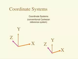
1.1 POLES, PLANES AND AXES • The orientation of axes of coordinate systems can be described in terms of primary and secondary poles, primary and secondary planes, and primary, secondary and tertiary axes. • The primary pole is the axis of symmetry of the coordinate system, for example the rotation axis of the earth. The primary plane is the plane perpendicular to the primary pole, for example the earth's equatorial plane. • The secondary plane is perpendicular to the primary plane and contains the primary pole. It sometimes must be chosen arbitrarily, for example the Greenwich meridian plane, and sometimes arises naturally, for example the equinoctial plane. The secondary pole is the intersection of the primary and secondary planes. The primary axis is the secondary pole.
The tertiary axis is the primary pole. The secondary axis is perpendicular to the other two axes, chosen in the direction, which makes the coordinate system either right-handed or left-handed as specified. • We will use either the primary plane or the primary pole, and the primary axis to specify the orientation of each of the coordinate systems named above.
The tertiary axis Z, X3 or 3. axis The primary pole The rotation axis of the earth The secondary plane The Greenwich meridian plane The secondary axis (for-left-handed system) Y, X2 or 2. axis The secondary axis (for right-handed system) Y, X2 or 2. axis Primary plane Earth’s equatorial Plane The primary axis X, X1 or 1. axis The secondary pole Figure 1.3- Poles, planes and axes
1.2 SUMMARY OF REFLECTION AND ROTATIONMATRICES 1.2.1 Orthogonal Transformations The matrix equation • Y = A X where A is a matrix and X and Y are columnvectors, can be regarded as a linear transformation, in which case the matrix A is called the transformation matrix. If the two vectors X and Y have the same length, then both the transformation and the matrix are said to be orthogonal. Orthogonal matrices have the property that the product of the matrix and its transpose (or vice versa) is the identity matrix, that is • AT A = A AT = I.
From this property it follows that the determinant of an orthogonal matrix is either +1 or -l. There are two kinds of orthogonal transformations called reflections and rotations. The determinant of reflection matrices is -1, and the determinant of rotation matrices is +1. There are two interpretations of the linear transformation above. The first is that the transformation describes the relationship between two coordinate systems, in which case X and Y are the same vector, but their elements refer to the two different systems. The second is that the transformation describes the relationship between different vectors X and Y in the same coordinate system. In these notes, we are interested only in the first interpretation.
1.2.2 Right and Left Handed Cartesian Coordinate Systems • A three dimensional Cartesian coordinate system can be orthogonally transformed in only six different ways. It can be rotated about each of its axes. Each of its axes can be reflected. In such a coordinate system, the vectors X and Y will have only three elements. Let us define the axis to which the first, second, and third elements of X and Y are referred as the 1-axis, 2-axis, and 3-axis respectively (we could equally well label them the xl, x2, x3 axes or x, y, z axes).
These three axes may define either a right-handed or a left-handed coordinate system. Right handed systems follow the right hand rule: if the fingers of the right hand are curled around any axis so that the thumb points in the positive direction, then the fingers will point from a second axis to the third axis, numbered in cyclic fashion. Grasping the 1-axis, the fingers point from the 2-axis to the 3-axis. Grasping the 2-axis, the fingers point from the 3-axis to the 1-axis. Grasping the 3-axis, the fingers point from the 1-axis to the 2-axis. Left-handed coordinate systems follow the left hand rule, which differs from the above only in that the left hand is used.
Z Z O Y Y O X X Figure 1.4a- Rigth-handed system Figure 1.4b- Left-handed system
1.2.3 Reflections • If we denote a reflection of the kth axis by Pk , then the following expressions define the three reflection matrices: ; ;(2.3) • Note that reflection matrices commute (e.g. P2P3 = P3P2), so that it makes no difference in what order a sequence of reflections are performed. Note also that an odd number of reflections changes the handedness of the coordinate system.
Rotations • In a Cartesian coordinate system with the axes x, y, z the position of a point P is determined by its position vector (2.5) • xP, yP, zP are real numbers (Fig. 1.5).
If we denote a rotation of angle about the 1st axis by R1(), a rotation of angle about the 2nd axis by R2(), and a rotation of angle about the 3rd axis by R3(), then the following expressions define the three rotation matrices:
Note that rotation matrices do not commute. The product of several rotations is performed from right to left, for example in R1() R2() R3(), the rotations are performed about the 3-axis of the original system, the 2-axis of the transformed system, and the 1-axis of the doubly transformed system, to yield the final triply transformed system.
The transformation to a second Cartesian coordinate system with identical origin and the axes x’, y’, z’, which is generated from the first one by a rotation around the z-axis by the angle , can be realized through the matrix operation XP = R3() XP(2.7) • The representation is valid for a right-handed coordinate system. When viewed towards the origin, a counter-clockwise rotation is positive. Any coordinate transformation can be realized through a combination of rotations. The complete transformation is XP = R1() R2() R3() XP(2.8)
Finally, the matrix for a general rotation by the angles , , is R = R1() R2() R3()(2.9) • The relation between the position vectors in two arbitrarily rotated coordinate systems is then • XP = R XP ; XP = RT XP (2.10)
In geodesy the rotation angles are often very small, thus allowing the use of the linearized form for R. With cos 1 and sin (in radians), neglecting higher order terms, it follows that (2.11) If the rotation angles are all so small that their cosines can be assumed to be unity, then the rotation matrices become commutative. This is the case for differential rotations, for example.
The above expressions define positive rotations, which are right-hand rotations for right-handed coordinate systems and left-hand rotations for left-handed coordinate systems. A right-hand rotation is related to the right hand rule given above: if the fingers of the right hand are curled around the rotation axis so that the thumb points in the positive direction, then the fingers curl in the direction of a right hand rotation. A similar statement for left hand rotations is obvious.
1.2.5 Inverse Transformations • The inverse of a transformation A (denoted A-1) is the transformation which returns conditions to their original state, that is A-1 A = A A-1 = I. • Reflections are self-inverse, that is PkPk = I • Common sense tells us that the inverse of a positive rotation is a negative rotation, that is and this conclusion is verified by taking the orthogonal property AT A = I from which it is evident that for orthogonal matrices A-1 = AT
and for each of the above expressions for rotation matrices it can be shown that Applying the rule for the inverse of products [A B]-1 = B-1 A-1 we have A product transformation consisting of one rotation and one reflection commutes only if the rotation and reflection refer to the same axis, that is PjRk = RkPj if j = k otherwise PjRk = Rk-1Pj if j k.
2. TERRESTRIAL COORDINATE SYSTEMS • In this chapter we will discuss terrestrial geocentric and terrestrial topocentric coordinate systems. • We first discuss terrestrial geocentric systems using only Cartesian coordinates, and considering in detail what is meant by "the earth's axis of rotation" and "the Greenwich meridian". Then the relationship between Cartesian and curvilinear coordinates is described. Geodetic datums are discussed. Finally terrestrial topocentric systems are considered, with attention paid to what is meant by "the surface of the earth".
2.1 TERRESTRIAL GEOCENTRIC SYSTEMS In the introduction it was stated that for terrestrial geocentric systems: • a) the origin is near the centre of the earth, • b) the primary pole is aligned to the earth's axis of rotation, • c) the primary axis is the intersection between the primary plane and the plane containing the Greenwich meridian, • d) the systems are right-handed. • The last specification is unambiguous. As we shall see the other three are not. We will first discuss problems in defining the earth's axis of rotation and the Greenwich meridian. Then we will discuss translations of the origin from the centre of the earth.
2.1.1 Polar Motion and Irregular Rotation of the Earth • We think of the earth as rotating about a fixed axis at a uniform rate. In fact, the axis is not fixed and the rate is not uniform. • Over 80 years ago, it was discovered that the direction of the earth's rotation axis moves with respect to the earth's surface. This polar motion is principally due to the fact that the earth's axes of rotation and maximum inertia do not coincide. The resultant motion is irregular but more or less circular and counterclockwise (when viewed from North), with an amplitude of about 5 meters and a main period of 430 days (called the Chandler period). • The earth rotation parameters cannot be described through theory but must be determined through actual observations by the international time and latitude services. For the last 80 years, or so, these services were based mainly on astronomical observations.
Two international organizations, the International Polar Motion Service (IPMS) and the Bureau International de 1'Heure (BIH) routinely measured this motion through astronomic observations; the IPMS from five stations at the same latitude, and the BIH from about 40 stations scattered worldwide. The results were published as the coordinates of the true rotation axis with respect to a reference point called the Conventional International Origin (CIO) which is the average position of the rotation axis during the years 1900-1905, Figure 2-1 shows the polar motion during 1969 as determined by IPMS and BIH. On January 1, 1988 the International Earth Rotation Service (IERS) took over this task. The principle observation techniques now used are Laser ranging to satellites and to the moon and Very Long Baseline Interferometry (VLBI).
Z ZAnlık 90o batı boylamı Y 90o batı boylamı Y CIO CIO Ortalama Kutup X 0o boylamı Greenwich XP YAnlık YP( P T anındaki gerçek kutup O Y X 0o boylamı Greenwich X XAnlık Şekil 2.6- Kutup hareketi
Tablo 2.3 Kasım-Aralık 1990 için kutup hareketi parametreleri POLE COORDINATES, UT1-UTC, AND GPS-UTC FROM BIH, CIRCULAR B ------------------------------------------------------------------------ MJD X-POLE Y-POLE UT1-UTC GPS-UTC DATE REMARKS (") (") (S) (S) 48199. 0.2260 0.1371 -0.25656 6. 90 11 4 DEF 48204. 0.2073 0.1253 -0.26741 6. 90 11 9 DEF 48209. 0.1928 0.1138 -0.27872 6. 90 11 14 DEF 48214. 0.1777 0.1044 -0.28971 6. 90 11 19 DEF 48219. 0.1623 0.0963 -0.30094 6. 90 11 24 DEF 48224. 0.1436 0.0900 -0.31241 6. 90 11 29 DEF 48229. 0.1251 0.0845 -0.32413 6. 90 12 4 DEF 48234. 0.1073 0.0799 -0.33518 6. 90 12 9 DEF 48239. 0.0904 0.0747 -0.34529 6. 90 12 14 DEF 48244. 0.0737 0.0698 -0.35502 6. 90 12 19 DEF 48249. 0.0550 0.0678 -0.36508 6. 90 12 24 DEF 48254. 0.0346 0.0681 -0.37551 6. 90 12 29 DEF
Over 40 years ago irregularities in the rotation of the earth were discovered (other than polar motion). There are three types of irregularities: seasonal variations probably due to meteorological changes or earth tides; secular decrease due to tidal friction; and irregular fluctuations. The seasonal variation is the only one of these presently being taken into account, and it is more or less reproducible from year to year, and produces a displacement along the equator of up to 15 meters with respect to a point rotating uniformly . throughout the year (see Figure 2-2). Because of this seasonal variation, the Greenwich meridian (the plane containig the earth's rotation axis and the center of the transit instrument at Greenwich Observatory) does not rotate uniformly. A fictitious zero meridian which does rotate uniformly (so far as the effects of polar motion and seasonal variations are concerned) is called the Mean Observatory or Greenwich mean astronomic meridian. Its location was defined by the BIH.
The mean Greenwich meridian; also named the Greenwich Mean Observatory (GMO) is defined through the nominal longitudes of all observatories which contributed to the former international time service (Bureau International de l`Heure (BIH)). Because of the inclusion of new satellite observation techniques and additional stations for the determination of time and pole coordinates during the last decade, this definition was no longer valid in a rigorous sense. It was put on a broader foundation with the introduction of the new International Earth Rotation Service (IERS) . In future, the CTS will be defined by a global network of fundamental stations whose coordinates are determined by the most precise observation techniques. Coordinate changes, caused by recent crustal movement, are also considered. In 1984 the Bureau International de 1`Heure (BIH) introduced such a terrestrial reference system, named BTS (BIH Terrestrial System), and this system is now maintained as the IERS Terrestrial Reference Frame (ITRF) .
2.1.2 Average and Instantaneous Terrestrial Systems The average terrestrial (A.T.) system is the ideal world geodetic coordinate system (see Figure 2-3): • a) Its origin is at the centre of gravity of the earth. • b) Its primary pole is directed towards the CIO (the average north pole of 1900-1905), and its primary plane is the plane perpendicular to the primary pole and containing the earth's center of gravity (the average equatorial plane). • c) Its secondary plane is the plane containing the primary pole and the Mean Observatory. The intersection of these two planes is the secondary pole, or primary axis. • d) It is a right-handed system.
Figure 2.3a – Average Terrestrial Coordinate System • We can then define the position vector Ri of a terrain point i in terms of its Cartesian coordinates x, y, z as 2-1
The instantaneous terrestrial (I.T.) system is specified as follows: • a) Its origin is at the centre of gravity of the earth. • b) Its primary pole is directed towards the true (instantaneous) rotation axis of the earth. • c) Its primary axis is the intersection of the primary plane and the plane containing the true rotation axis and the Mean Observatory. • d) It is a right-handed system.
The main characteristic of these two systems is that they are geocentric systems having their origins at the centre of gravity of the earth and the rotation axis of the earth as the primary pole. • By means of rotation matrices the coordinates of a point referred to the instantaneous terrestrial system are transformed into the average system by the following equation (see Figure 2-4): 2-2
where (xP , yP ) are expressed in arcseconds, and the rotation matrices are a clockwise (negative) rotation about the x axis, and a clockwise (negative) rotation about the y-axis,
The inverse is and because of the orthogonal characteristic of rotation matrices, that is R-1() = RT() = R(-) 2-3