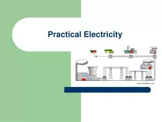
Practical Electricity, part 2
Practical Electricity, part 2. Ev I R P OHMS LAW. Skin effect?. hFE current gain. chassis. chassis. Diodes in action. Turn Sig. chassis. chassis. Agenda. Voltage Current Resistance Power, Volt Amps Symbology Single Phase Three Phase. 1. Power Source. 2. Conductors.

Practical Electricity, part 2
E N D
Presentation Transcript
Practical Electricity, part 2 Ev I R POHMS LAW
Skin effect? hFEcurrent gain
chassis chassis Diodes in action Turn Sig chassis chassis
Agenda • Voltage • Current • Resistance • Power, Volt Amps • Symbology • Single Phase • Three Phase
1.Power Source 2. Conductors 3. Load Simplified Circuit Circuits • Electric Circuits Consist of Three Parts : • 1. Power Source – Battery, Solar Cell, • 2. Conductors - Connecting Wires • 3. Load - Device such as, Motors, Lights, Heating etc.
Squirrel Power STATIC “VOLTAGE TYPES” CHEMICAL SOLAR
Voltage • Voltage (EMF Electromotive Force) • Volts (E or V) = Measurement of electrical force or pressure. • Similar to pressure. • Expressed as Electromotive Force (E) or (emf) in Ohm’s Law. • Common Units: • Microvolt (uV) = 1/1,000,000 Volt • Millivolt (mV) = 1/1000 Volt • Volt = 1 • Kilovolt (kV) = 1000 Volts
“Difference of Potential” • Difference of Potential = • Is the force that causes free electrons to move through a conductor as an electric current is referred to as difference of potential or often shortened to “potential”. • Similar to liquid flow there must be a difference in pressure or “differential pressure” or there will be no flow.
Analogy to Liquid Level “Difference of Potential” Difference of Potential Level Liquid Pressure Valve
Power Source Load Difference of Potential Switch Tank A Tank B “Difference of Potential” • When a difference in potential exists between two charged bodies that are connected by a conductor, electrons will flow until the two charges are equalized.
“CURRENT” • Electric Current = • The flow of electrons through conductive materials when electricity is being converted to useful work. • Two Electric Current Types • Direct Current (DC) • Alternating Current (AC)
“CURRENT” • Measurement of Amperage (Current Flow) • Amperes or “Amps” (A) = The measurement of current flow through a conductor (wire). • Number of (electrons) that pass through a given point, in a second. • Expressed as Intensity (I) in Ohm’s Law • Common Units: • = 1 Amp • Milliamp (mA) = 1/1000 Amp .001A 1 ma • Microamp (uA) = 1/1,000,000 Amp .000001A 1µa
“RESISTANCE” • Resistance (Opposition to Current Flow) • Ohm (W) = Measurement of resistance in an electrical circuit. • Similar to restriction of liquid or gas flow. • Expressed as Resistance (R) in Ohm’s Law. • Common Units: • Ohms (W) = 1 Ohm • Kilohms (k W) = 1000 Ohms • Megohms (meg W) = 1,000,000 Ohms • Every load on an electrical circuit creates resistance. • Resistance to the current load creates heat.
*Circular Mils = the standard unit of measurement of a round wire cross-sectional area The area in circular mils of a round conductor is obtained by squaring the diameter, measured in mils. The OHM
“IMPEDANCE, DC ” Z • IMPEDANCE – Algebraic sum of all the Resistance in the circuit. • For DC = Z is the same as the total resistance of the circuit ( Rt )
100 Psig 98.36 Psig Pressure Drop 1000 ft. 1” Pipe - 100 Psig water pressure - 1 GPM flow Voltage Drop “VOLTAGE DROP” • Resistance and Voltage Drop 100 Volts 98.38 Volts 1000 ft. 12 Gage Wire - 100 Volts - 1 Amp Current flow
Power In Back to the Future, Doc Emit Brown declares that it takes 1.21 gigawatts to travel through time. The gigawatt is a unit of power, not energy. Now, a gigawatthour is a unit of energy.
“POWER” “WATT” • Electrical Power (Horsepower) • Watt (W) = 1 Watt = 1 Volt times 1 Amp of current • Expressed as (P) in power calculation formulas. • 746 Watts = 1 Horsepower. • 1 HP = ¾ KiloWatt Common Units: 1 Microwatt = 1/1,000,000 Watt 1 Milliwatt = 1/1000 Watt 1 Kilowatt = 1000 Watts 1 Megawatt = 1,000,000 Watts 1 GigaWatt = 1 Billion Million Watts Kilowatt Hour = Kilowatts used in 1 hour
Review Discussion • Voltage is a measurement of: • electrical force (similar to pressure) • Amperage is a measurement of • current flow (similar to flow) • Ohm is a measurement of • resistance to current flow (similar to restriction) • Wattage is a measurement of • power used to perform work (horsepower)~ • Voltage Drop is the result of • the corresponding result of opposition to current flow.
2 More Electrical Terms • Inductance (Coil, transformer) • Capacitance (Capacitor) • Factors present in an AC circuit because the current is operating at 60 HZ, frequency dependant. 1 XC= 2π f C XL= 2π f L
AC Current Relationships • Current thru Resistor is in phase • Current thru Inductor will lag 90 • Current thru Capacitor will lead by 90 • Magnitude of current thru RLCwill dependent on Impedance which is a vector sum • POWER FACTOR CORRECTION • Capacitor Banks
Resistive vs Inductive ELI ICE MAN Voltage leads Current in a inductive circuit Current leads voltage in a capacitive circuit
Electrical Theory Basic Formulas - Ohm’s Law • Law 1 -If the voltage remains constant the current is inversely proportional to the resistance • Law 2 - If the current remains constant the emf voltage across a device varies directly with the resistance • Law 3 - If the resistance remains constant the current varies directly with the applied voltage I R V = EMF in Volts I = Intensity in Amps R = Resistance in Ohms V
I V P Electrical Theory Basic Formulas - Calculating Power • The basic formulas used for calculating power as it is related to volts of emf, Amps of current. and resistance are contained in the following summary pie graph. P = I x V P = Power in Watts I = Intensity in Amps V = EMF in Volts
Electrical Theory Summary of Basic Formulas
Calculate Resistance (Handout) • Resistors in series • Resistors in parallel • Resistors in combination
Calculate Current • Current is same in series (Rt) • Current in parallel adds (Rt)
Calculate Power • Power Adds in parallel
Wires, Connected, Crossing Wires, Not Connected, Crossing Symbology
A B C A 3 Coils in GeneratorCycles are 120 degrees apart A B C AC 3 Phase