Download
1 / 13
130 likes | 258 Vues
Upper mantle velocity structure of the Arabian Shield from body and surface wave tomography. Andy Nyblade, Penn State University Yongcheol Park, Korean Polar Research Inst. Artie Rodgers, LLNL Abdullah Al-Amri, King Saud University Margins RCL workshop, April 30, 2009.

E N D
Upper mantle velocity structure of the Arabian Shield from body and surface wave tomography Andy Nyblade, Penn State University Yongcheol Park, Korean Polar Research Inst. Artie Rodgers, LLNL Abdullah Al-Amri, King Saud University Margins RCL workshop, April 30, 2009
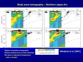
Park et al. G-Cubed, 2007 • Limited station distribution in middle of the shield and large station spacing • Limited resolution above 150 km depth and across middle of shield at all depths • Favor single plume (Afar) or superplume model (African superplume)
Park et al. G-Cubed, 2007 • Limited station distribution in middle of the shield and large station spacing • Limited resolution above 150 km depth and across middle of shield at all depths • Favor single plume (Afar) or superplume model (African superplume)
Rayleigh wave tomographyPark et al. G-Cubed, 20081) Data: SANDSN; PASSCAL - S. Arabia, Ethiopia; GSN/FDSN 2) MFT (Dziewonski et al., 1969) used for interstation phasevelocities3) Method of Lawrence et al., 2006 (modified from Menke & Levin, 2002) used to correct for wavefront distortion 4) 45 to 140 sec period5) Method for inversion: LSQR (Paige and Saunders, 1982)
Inversion for structure1) 1D models for each grid point using linearized iterative method of Julia et al (2003)2) included group vel. 10-45 sec period from Pasyanos (2005)3) Model parameterization: crust 4 or 5 layers (Crust 2.0), 10 km thick layers in mantle4) Moho depth and Sn fixed to be consistent with previous results5) Quasi-3D model obtained by combining 1D models (interpolating between them at 10 km depth intervals using min. curvature gridding algorithm)
Shield Platform Shield Platform
Other relevant geophysical observations Normal 410 and 660 km discontinuities (Kumar et al., 2002; Benoit et al., 2003) 2) Dynamic uplift (Daradich et al., 2003; Hansen et al., 2007) 3) Seismic anisotropy: N-S fabric (Hansen et al. 2007; Tkalcic et al., 2006) 4) Seismic models supporting African superplume; lower- upper mantle connection (Benoit et al., 2006; Simmons et al., 2007; Ritsema et al., 1999)
Moho Depths Crust 2.0 (Bassin et al., 2000) Al-Damegh et al., 2005; Kumar et al., 2002; Mooney et al., 1985