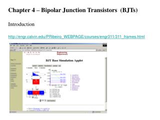
Chapter 4 Bipolar Junction Transistors
Chapter 4 Bipolar Junction Transistors. Objectives. Describe the basic structure of the bipolar junction transistor (BJT). Explain and analyze basic transistor bias and operation. Discuss the parameters and characteristics of a transistor and how they apply to transistor circuits.

Chapter 4 Bipolar Junction Transistors
E N D
Presentation Transcript
Objectives • Describe the basic structure of the bipolar junction transistor (BJT) • Explain and analyze basic transistor bias and operation • Discuss the parameters and characteristics of a transistor and how they apply to transistor circuits • Discuss how a transistor can be used as an amplifier or a switch • Troubleshoot various failures typical of transistor circuits
Introduction A transistor is a device that can be used to either switch flow on/offor “control flow” device. Let’s first consider its operation in a simpler view as a flow switching device. + ollector - ollector I I I 1 - open 2 - closed mitter mitter - + On/Off Flow
Introduction Let’s first consider its operation in a simpler view as a current controlling device. + - ollector ollector I I I I Variable Flow - + mitter mitter Flow
Transistor Structure With diodes there is one p-n junction. With bipolar junction transistors (BJT), there are three layers forming two p-n junctions. Transistors can be either pnp or npn type.
Physical construction of a BJT is deposited layers of “doped “ N and P semiconductor materials. BJT Construction Note: Epitaxial films may be grown from gaseous or liquid precursors. Because the substrate acts as a seedcrystal, the deposited film takes on a lattice structure and orientation identical to those of the substrate. This is different from other thin-film deposition methods which deposit polycrystalline or amorphous films, even on single-crystal substrates. If a film is deposited on a substrate of the same composition, the process is called homoepitaxy; otherwise it is called heteroepitaxy.
Basic Transistor Operation • Look at this one circuit as two separate circuits: • The base-emitter (left side) circuit and • The collector-emitter (right side) circuit. • Note that the emitter leg serves as a conductor for both circuits. • The amount of current flow in the base-emitter circuit controls the amount of current that flows in the collector circuit. • Small changes in the transistor base-emitter current yields a large change in collector-current. IE = IC + IB http://www.bcae1.com/transres.htm
Basic Transistor Operation Below, is the proper bias configuration for the npn and the pnp transistor. Note that base-emitter junction is forward-biased, while the base-collector junction is reverse-biased (known as forward-reverse bias). For the npn, the forward-bias BE, narrows the BE junction depletion zone, while the reverse-bias BC depletion zone grows larger. Let’s examine this more closely (next slide). IC = ß IB Forward-Reverse bias of a bipolar transistor.
Basic Transistor Operation - Conventional Flow • Looking at a forward-reverse bias NPN • Forward-bias BE narrows “Depletion Zone” (see forward-biased diode). • Reverse-bias BC widens “Depletion Zone”. • Emitter (doped) region is “rich” with free (conduction-band) electrons. • These “conduction-band” electrons easily migrate across the BE junction to become “minority carriers” in the base. • Since there are few “holes, only a few recombine to form a small “valence electron current” thru RB to BE supply. • The “free electrons” are attracted across the BC junction into the Collector and thru to the +C supply as Ic (collector current). • The PNP transistor follows a similar logic. NPN Transistor Collector “valence electron” current 6 2 5 4 Base 1 3 Emitter
Transistor Currents (Conventional Flow) IE = IC + IB Note relative current sizes.
Regions of operation • Applied voltages Mode • E < B < C Forward active • E < B > C Saturation • E > B < C Cut-off • Forward active: base higher than emitter, collector higher than base (in this mode the collector current is proportional to base current by βF). • Saturation: base higher than emitter, but collector is not higher than base. • Cut-Off: base lower than emitter, but collector is higher than base. It means the transistor • is not letting conventional current to go through collector to emitter.
In terms of junction biasing: ('reverse biased base–collector junction' means Vbc < 0 for NPN, opposite for PNP) • Forward-active (or simply, active): The base–emitter junction is forward biased and the base–collector junction is reverse biased. Most bipolar transistors are designed to afford the greatest common-emitter current gain, βF, in forward-active mode. If this is the case, the collector–emitter current is approximately proportional to the base current, but many times larger, for small base current variations. • Saturation: With both junctions forward-biased, a BJT is in saturation mode and facilitates high current conduction from the emitter to the collector. This mode corresponds to a logical "on", or a closed switch. • Cutoff: In cutoff, biasing conditions opposite of saturation (both junctions reverse biased) are present. There is very little current, which corresponds to a logical "off", or an open switch.
There are basically three possible ways to connect a Bipolar Transistor within an electronic • circuit with each method of connection responding differently to its input signal as the static characteristics of the transistor vary with each circuit arrangement. • 1. Common Base Configuration - has Voltage Gain but no Current Gain. • 2. Common Emitter Configuration - has both Current and Voltage Gain. • 3. Common Collector Configuration - has Current Gain but no Voltage Gain
Transistors Characteristics and Parameters For proper operation, the base-emitter junction is forward-biased by VBBand conducts just like a diode. IB is set. The collector-base junction is reverse biased by VCC and blocks current flow through it’s junction just like a diode. Current flow through the base-emitter junction will help establish the path for current flow from the collector to emitter. BC Reverse-biased IC + IB results in IE BE Forward-biased
Transistor Characteristics and Parameters Analysis of this transistor circuit to predict the dc voltages and currents requires use of Ohm’s law, Kirchhoff’s voltage law and the ß for the transistor. Determine the base BIAS current. Using Kirchhoff’s voltage law, subtract the 0.7VBE from VBB and the remaining voltage is dropped across RB. Determining the current for the base with this information is a matter of applying of Ohm’s law. VRB/RB = IB (ohm’s law) The collector DC current is determined by multiplying the base current by beta.ICdc = IBdc orDC = IC/IB Note: 0.7 VBE will be used in most analysis examples.
Transistor Characteristics and Parameters What we ultimately determine by use of Kirchhoff’s voltage law for series circuits is that; In the base circuit, VBB is distributed across the base-emitter junction and RB in the base circuit. In the collector circuit we determine that VCC is distributed proportionally across RCand the transistor (VCE).
Transistor Characteristics and Parameters • SmallΔIDCbase-emitteryieldsLargeΔIDCcollector-emitter • This relationship of current change (collector to base) • (ΔIDCcollector-base)is calledbeta. ( ) ∝ DC = IC/IB (Current Gain) Data sheets will refer to hybrid (h) parameters hFE = DC (typical hFEvalues 20 – 200) • The relationship of current change (collector to emitter) • (ΔIDCcollector-emitter) is called alpha. (∝) • ∝DC = IC/ IE is always >1. • (Typical ∝ values0.95 – 0.99+) See Ex. 4-1
Transistor Characteristics and Parameters There are three key dc voltages and three key dc currents to be considered. Note that these measurements are important for troubleshooting. Relationships of Key Parameters: VBE= 0.7 V. IB = (VBB – VBE)/RB VCE =VCC –ICRC VCB = VCE -VBE IB: dc base current IE: dc emitter current IC: dc collector current VBE: dc voltage across base-emitter junction VCB: dc voltage across collector-base junction VCE: dc voltage from collector to emitter See Ex 4-2
Collector Characteristic Curves Collector characteristic curves give a graphical illustration of the relationship of: Ic (collector current), and VCE (Voltage-Collector to Emitter) with specified amounts of IB(base current). With greater increases of VCC , VCE continues to increase until it reaches breakdown, but the current remains about the same in the linearregion from .7V to the breakdown voltage. IBase IC Ic Linear Region Ic IB Vcc VCE Cutoff region VCE VCE Active Region See Ex. 4-2
Transistor Characteristics Curves - Review 1.Vcc = 0 IB is thru the base & emitter. Transistor is in Saturation 2. VCC , VCE and Ic with increase Vcc 3. VCE exceeds 0.7V Base/Collector junction is reverse-biased Transistor operates in Linear region 4. “breakdown” or Avalanche region. ……. Bad!! 4 3 2 2 1 See Ex. 4-3
Transistor Characteristics and Parameters With no IB this transistor is in the cutoff region and just as the name implies there is practically no current flow in the collector part of the circuit. With the transistor in a cutoff state the full VCC can be measured across the collector and emitter (VCE). Rc≈0V.
Transistor Characteristics and Parameters Current flow in the collector part of the circuit is, determined by IB multiplied by . However, there is a limit to how much current can flow in the collector circuit regardless of additional increases in IB. Once this maximum is reached, the transistor is said to be in saturation. Note that saturation can be determined by application of Ohm’s law. IC(sat)=VCC/RC The measured voltage across the now “shorted” collector and emitter is VCE = 0V.
Transistor Characteristics and Parameters The dc load line graphically illustrates IC(sat)and cutoff for a transistor. NOTE: This will be the area of operation for all out transistor applications. See Ex.4-4
Transistor Characteristics and ParametersMore about β The beta for a transistor is not always constant. Temperature and collector current both affect β. Variances in the manufacture of the transistor may also result in variable β’s. There are also maximum power ratings to consider. The data sheet below, provides information on these characteristics. Note:ΔβDC for various temperatures. Note: ΔβDCfor ΔIC See End of Chap. Q.4-20 & 21
Transistor Characteristics and ParametersMaximum Power Ratings • Maximun ratings are available from datesheets and on-line. • Typical max. ratings address: VCE max, VCB max, VEB max, IC max & Power. • A primary limitation is; Ic = PD(max) / VCE rearranged: VCE = PD(max)/IC • Power: P= EI, P= I2R, P=E2/R Assuming PD(MAX) is 500mW: VCEmax is 20V, IC(MAX) is 50mA. The graph shows the transistor can’t be operated in the “shaded“ areas. IcMAX PDMAX VCE(MAX) See Ex. 4-5 & 4-6
Power Derating – PDmax 3 factors decide Power Deratings: see the previous slide. ICmax , VCEmax & PDmax -------- IC = PD(max) / VCE See the Datasheet for Deratings Transistor Characteristics and ParametersPower Derating/Data Sheets See Ex. 4-7 • Transistor Datasheets • Provide: • Physical details • Absolute Maximum ratings: • Voltage, Current, Temperature & Power • Thermal characteristics • Electrical Characteristics – hfe, Cutoff, Breakdown voltage, Gain, Capacitance, Switching speeds, etc. See Ex. 4-8
BJT (Transistor) Amplifier Amplification is the process of linearly increasing the amplitude of an electrical signal. Some designation standards and conventions: DC Currents:IC IEIB DC Voltages: VBE VCB VCE VB VC VE External DC Resistance: RERCRB AC Currents: Ic Ie Ib AC Voltages: Vbe Vcb Vce Vb Vc Ve ExternalAC Resistances: ReRcRb Internal Transistor Resistances: r ’ r ’e
Transistor Switch A transistor when used as a switch is simply being biased so that it is in cutoff (switched off) or saturation (switched on). Remember that the VCE in cutoff is VCC and 0 V in saturation. VCE(cutoff) = VCC IC(sat) = VCC – VCE(sat) βDC IB(min) = Ic (sat) See Ex 4-10 βDC
Transistor Switch Application: Transistor Switch Base of transistor is “pulsed” with a “squarewave”. “Off” periods provide no base biasing….transistor remains OFF. “On” periods provide DC bias, switching the transistor “ON” IB is max. Ic is max. LED lights!! See Ex 4-11
Transistor Types & Packaging 2N3904 2N3906 Same transistor type in metal packaging
Transistor Types & Packaging RF Transistors High-density, multi-transistor packaging Power transistors
Troubleshooting Troubleshooting a live transistor circuit requires us to be familiar with known good voltages, but some general rules do apply. Certainly a solid fundamental understanding of Ohm’s law and Kirchhoff’s voltage and current laws is imperative. With live circuits it is most practical to troubleshoot with voltage measurements.
Troubleshooting Opens in the external resistors or connections of the base or the circuit collector circuit would cause current to cease in the collector and the voltage measurements would indicate this. Internal opens within the transistor itself could also cause transistor operation to cease. Erroneous voltage measurements that are typically low are a result of point that is not “solidly connected”. This called a floating point. This is typically indicative of an open. More in-depth discussion of typical failures are discussed within the textbook.
Troubleshooting Testing a transistor can be viewed more simply if you view it as testing two diode junctions. Forward bias having low resistance and reverse bias having infinite resistance.
Troubleshooting The diode test function of a multimeter is more reliable than using an ohmmeter. Make sure to note whether it is an npn or pnp and polarize the test leads accordingly.
Summary • The bipolar junction transistor (BJT) is constructed of three regions: base, collector, and emitter. • The BJT has two pn junctions, the base-emitter junction and the base-collector junction. • The two types of transistors are pnp and npn. • For the BJT to operate as an amplifier, the base-emitter junction is forward-biased and the collector-base junction is reverse-biased. • Of the three currents IB is very small in comparison to IE and IC. • Beta is the current gain of a transistor. This the ratio of IC/IB.
Summary • A transistor can be operated as an electronics switch. • When the transistor is off it is in cutoff condition (no current). • When the transistor is on, it is in saturation condition (maximum current). • Beta can vary with temperature and also varies from transistor to transistor.