Download
1 / 103
1.15k likes | 1.44k Vues
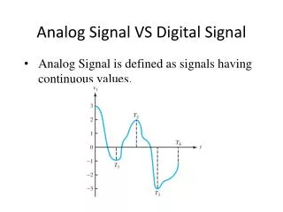
Learn basics of ECG signal chain, electrode modeling, lead derivation, and INA front end with ADS129x. Explore cost-effective ECG system design through TINA/SPICE simulations.

E N D
Analog Fundamentals of the ECG Signal Chain Prepared by Matthew Hann, Texas Instruments Precision Analog Applications Manager
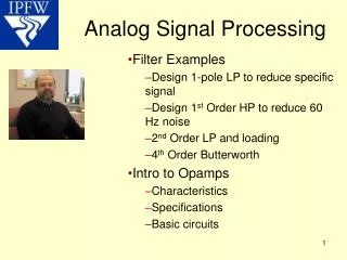
Objectives • Introduce Basic ECG Concepts • Motivate the Need for TINA and SPICE Simulation for ECG Analysis • Introduce Discrete Analog Functions of the ECG Signal Chain • Motivate Need for Low Cost Integrated ECG Conditioning System • Introduce the ADS1298 and Its Embedded ECG Circuitry and Functions
Analog Fundamentals of the ECG Signal Chain • What is a Biopotential? • What is ECG? • The Einthoven Triangle • Analog, Lead Definitions, Derivations, and Purpose • Modeling the Electrode Interface • Input Filtering and Defibrillation Protection • The INA front end • AC vs. DC coupling • RL Drive Amplifier Selection and Design • The ECG Shield Drive • Lead Off Detection • PACE Detection • INA post Gain + Analog Filtering • A/D Conversion Options and Filtering • ADS129x Introduction, Features, and Advantages
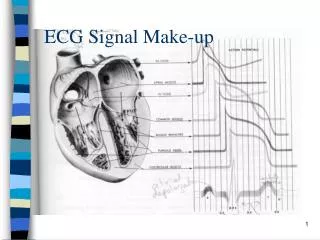
What is a BiopotentialAn electric potential measured between living cells
What is ECG?A measure of the electrical activity of the heart
What is ECG?ECG irregular tracings due to external artifacts
What is ECG?Modeling the electrode interface Electrical characteristics include a DYNAMIC resistance, capacitance, and offset voltage
Einthoven’s Law In electrocardiogram at any given instant the potential of any wave in Lead II is equal to the sum of the potentials in Lead I and III. Analog Lead DerivationECG Einthoven Triangle, 1907 3 Body Electrodes, 3 Derived Leads = I, II, III LEAD I = VLA-RL – VRA-RL LEAD II = VLL-RL – VRA-RL LEAD III =VLL-RL – VLA-RL Right Leg Reference, RL
Analog Lead DerivationThe Wilson Central (WCT) Provides Chest Lead Reference at Center of Einthoven Triangle Assuming: RRA = RLA = RLL Then: *Drawing Taken From Bioelectromagnetism, Jaako Malmivuo and Robert Plonsey
The Wilson Central is used to derive a reference potential for the Chest Leads, V1 – V6 Analog Lead DerivationThe Wilson Central is the AVERAGE potential between RA, LA, and LL RRA VOUT = V(1-6) - VWCT RLA RLL
Different Chest Leads Provide: *Unique ECG Signature *Enhanced Pattern Recognition *Isoelectric Point @ V3-V4 Analog Lead DerivationChest Lead Signals Provide Different Information at Different Cross-Sectional Angles
Analog Lead DerivationAugmented Leads Derived via WCT to Provide Enhanced Vector Information • Each lead provides unique information about the ECG Output Signal • Multiple Angles Give a Better Than 2-D Picture of the ECG Output • AVR, AVL, AVF derived via midpoint of 2 limbs (resistor divider) with Respect to 3rd limb
Analog Lead DerivationIEC60601-2-51—Diagnostic Standards Electrodes Needed 1 Lead LA, RA 3 Lead LA, RA, LL 6 Leads LA, RA, LL 12 Leads LA, RA, LL, V1-6
Left Axis Deviation (LAD) and = + Analog Lead DerivationDifferent Lead Combinations Reveal Axis Deviation QRS in AVF QRS in LEAD I Mean QRS Vector Points Toward Area of Infarction (Damage)
Analog Lead DerivationDifferent Lead Combinations Reveal Axis Deviation I I AVF AVF I I AVF AVF
ECG Input Filtering, Defibrillation Protection, and Isolation
ECG Input Filtering and ProtectionExample: LEAD I Protection with Input Filtering CF, Ccm, and Cdiff + Rfilter form LPF Series Resistance Limits Input Current Protection Diodes +Vs Rfilter2 RPatient Rfilter1 LA CF CCM +Vs NE2H Zener Diode Cdiff -Vs Rfilter2 Rfilter1 RPatient RA CCM CF NE2H -Vs Patient Protection 10 -20k ohms Ne2H Lamps/TVS Protect Against Defibrillation Voltages Cdiff = 10 x Ccm
System Block Diagram INA Wilson MUX QRS and PACE Detect I dV/dt II RA III LA aVR LL aVL aVF RL Filter Isolation MUX WCT INA A/D V1 V2 DIO V3 V4 V5 V6
The INA Front EndKey Features of the INA Front End *Important* Less Important • Input Bias Current • Input Impedance • Input Current Noise • Input Voltage Noise • Power Consumption • DC/AC CMRR • Input Offset Voltage • Input Offset Voltage Drift • Gain Error • Nonlinearity • PSRR *DC Errors such as VOS are swamped out by the Offsets Introduced by the Skin-Electrode Contacts
The INA Front EndIdeal Simulation Circuit with Current and Voltage Noise Sources ECG + Skin Impedance Input CM + Differential Filtering Electrode Impedance + Offset Ideal INA Front End
The INA Front EndSimulation Showing Output-Referred Total RMS Noise vs. Bandwidth (G = 1-10) Noise may NOT necessarily increase linearly with gain (INA or PGA topology dependent)
The INA Front EndTINA Simulations Showing Output-Referred ECG Signal (G = 1-10) Snapshot of R Wave from ECG Waveform ECG Signal Varies LINEARLY with Increase in Gain
The INA Front EndWhat is the MAX gain on the INA When Using a DC Removal Circuit? Integrator Removes Gained up DC offsets and servos INA output to Vref (3) Vref (2) (1) (1) Electrode Offset MAX = +/- 300mV (2) Swing of INA = V(+) – 50mV (3) Integrator Compliance = (ECGp + ECGn +VOS + VOSelectrode)* Gain < VCC - Vref
The INA Front EndSimulation Circuit with Ideal INA and Vref = 2.5V as Integrator Input OPA333 Used as Integrator to Remove DC and Simulate Real Response During Saturation
The INA Front EndECG + Integrator Output of INA vs. Gain for Vref = 2.5V As the output of the Integrator Saturates from Increased Gain, Vout of the INA pulls away from Vref
The INA Front EndIf it is Advantageous to Maximize Gain with a Low Noise INA up Front, Why not AC Couple? ECGp VCM + ECGp + VOSelectrode1 (ECGp –ECGn)*Gain VCM + ECGn + VOSelectrode2 ECGn *AC Coupling Removes Electrode Offsets so that Higher Gain Can Be Used for Potentially Better SNR in the Signal Chain Path
The INA Front EndTINA Simulation Circuit to Show AC-Coupled INA Gain Sweep
The INA Front EndINA Gain = 1-1000 with VREF = 2.5V AC Coupled
The INA Front EndWhat is CMRR? Why is it Important in ECG? ECGp VCM Lower CMRR = More Unwanted Output Signal ECGn
The INA Front EndWhat is CMRR? Why is it Important in ECG? RP1 ECGp CC1 The INA includesthe R and C and must be considered in the overall CMRR Analysis VCM CC2 ECGn RP2 • Mismatch in Rp and Cc causes a differentialsignal error • Even a 1% tolerance on Cc cause a 20dB attenuation in CMRR
The INA Front End50/60Hz Common Mode Simulation Circuit with 1µF Coupling Capacitors Mismatched CMR TINA Circuit Test By Sweep of Mismatch of Input Coupling Capacitors
.5% Mismatch 0% Mismatch The INA Front EndPlot of CMRR vs. Frequency for .01 - .5% Coupling Capacitor Mismatch
The INA Front EndPlot of ECG Response to 5Hz CM Input Signal (0%-.5%) CC Mismatch Lower Frequency Signals Couple Directly Into the ECG Signal to the Output
The INA Front EndPlot of ECG Response to 50/60 Hz CM Input Signal • 50/60Hz Noise Rejection is Virtually Unaffected by AC Coupling • Dependent Primarily on the Noise Magnitude and the CMRR of the Front End INA
The RL Drive AmplifierThe RL Drive Amplifier Serves 2 Purposes: (1) Common Mode Bias (2) Noise Cancellation ECGp CMnoise CMnoise ECGn Average VCM is Inverted and Fed Back to RL; Cancels 50/60Hz noise *Tapping off center of split gain resistor feeds the following voltage to the RL Drive Circuit [(Vcm+ ECGP )+ (Vcm+ ECGn )]/ 2 = Vcm + (ECGp + ECGn )/2
The RL Drive Amplifier Simulation Circuit for Response to 50/60 Hz CM Noise Injection Source = Included for TINA spice Convergence
The RL Drive Amplifier TINA Simulation with NO RL Drive; CM Noise is Coupled to Output
The RL Drive Amplifier TINA Simulation with RL Drive; Output Noise is Reduced
The RL Drive Amplifier Analyzing the RLD Amplifier Loop VECGp + Vep + VCM ECGp Vep RA RG/2 RG/2 RA • More Gain = Better CMRR • Loop Corrects for Electrode Offset, VOSA1, and VOSRLD RF Ven ECGn VREF RI VECGn + Ven + VCM
The RL Drive Amplifier Simulation Circuit for CMRR of RLD Loop Sweep Feedback Resistor Gain to show Effects of CMRR @ 50/60Hz