Download
1 / 119
1.42k likes | 2.25k Vues
ECG signal acquisition hardware design. University of Alabama ECE Department. Background. ECG/EKG ( electrocardiogram) Records the heart's electrical activity: Heart beat rate Heart beat rhythm Heart strength and timing.

E N D
ECG signal acquisition hardware design University of Alabama ECE Department
Background • ECG/EKG (electrocardiogram) Records the heart's electrical activity: • Heart beat rate • Heart beat rhythm • Heart strength and timing
Note: The last slide has all references these slides have referred to.All these slides cover the major ideas of ECG sensor design from 9 journal papers (References [1] – [9])
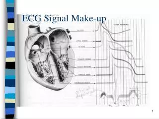
Background ECG works mostly by detecting and amplifying the tiny potential changes on the skin that are caused when the electrical signal in the heart muscle is charged and spread during each heart beat. This is detected as tiny rises and falls in the voltage between two electrodes placed either side of the heart.
Background • The heart's electrical system: • Sinoatrial(SA) node • Atrioventricular(AV) node • His-Purkinje system
Background P wave: signal spread from SA node to make the atria contract. P-Q Segment: signal arrives AV node stay for a instant to allow the ventricle to be filled with blood. Q wave :After the Buddle of His the signal is divided into two branches and run through the septum. R,S wave: Left and right ventricle contraction are marked by the R,S wave. T wave: ventricle relaxing Schematic representation of normal ECG
ECG SIGNAL • ECG bio-signal typical specifications: • low differential voltage from 0.4 to 3 mV • high common-mode rejection ratio level • low frequency range • high noise
ECG SIGNAL • Artifacts (disturbances) can have many causes. Common causes are: • Movement Sudden movement Baseline drift
Ecg signal • Electrical interference From a nearby electrical appliance. A typical example is a 100 Hz background distortion from fluorescent lights. To be confused with atrial fibrillation.
ECG electrode • Lead • The signal recorded as the difference between two potentials on the body surface is called an "ECG lead". Each lead is said to look at the heart from a different angle.
Electrode • Lead position Lead III Lead 12
ECG electrode A typical surface electrode used for ECG recording is made of Ag/AgCl, as shown on right Figure . The disposable electrodes are attached to the patients’ skin and can be easily removed. • Limb Leads (Bipolar) • Chest Leads (Unipolar) • Augmented Limb Leads (Unipolar) Wet, dry and insulating…
Design(1) • A 0.5-uVrms 12-uW Wirelessly Powered Patch-Type Healthcare Sensor [1] • Thick-film electrodes • Fabric inductor • W-BSN controller • Desired Circuit Design (LDO , NCA, PGA, ADC)
Design(1) • Advantages: • Long-term continuous monitoring, comfortable without skin irritation • Wireless powered without battery through fabric inductor coupling is realized. • Low electrode referred noise by NCA • Small IC size (2.6 mm2 ) • Convenience and Safety
Design(1) • System Architecture: Controller on chest band: 12 x 4 inductor array and W-BSN controller. sensors are attached at arbitrary locations. automatically finds the locations and activates each sensor by self-configuration
Design(1) • System Architecture: B. Wireless powered Sensor: Two dry electrodes Sensor chip P-FCB inductors Adhesive bandage Take the power overhead from the sensors, moving it to the relatively power-sufficient health monitoring chest band.
Design(1) • Requirements: • Sensor IC must consume power in total of less than 20 uW. • The noise contribution of the sensor readout front-end must be less than 1 uVrms. • The contact impedance and the motion artifacts of the dry fabric electrode must be minimized
Design(1) Electrode Design: Wet electrode: uncomfortable, good conduction, short time Plaster electrode: Stiff, uncomfortable, motion artifacts Fabric electrode: Soft, comfortable, long term A silver paste is screen printed directly on a fabric, a stainless steel powder with grain size of 100 um is added on top of the silver paste.
Design(1) • Noise and Artifacts A. Electrode Noise: B. Motion Artifacts:
Design(1) • System Architecture:
Design(1) • LDO Regulator Generated voltage(VDD) is regulated by an LDO regulator to create an internal silent supply voltage (VDDR) of 1.7 V, and it is dispatched to the NCA, PGA and ADC.
Design(1) B. NCA (nested chopping amplifier) • Chopper amplifier A chopper amplifier is a type of amplifier that exhibits precise outputs and low noise. Reduces the offset from part to part. Reduces the offset over time Reduces the offset over temperature. Reduces offset over common mode voltage.
Design(1) B. NCA (nested chopping amplifier) • Nested Chopping amplifier A LPF generates a residual offset proportional to its chopping frequency, and it may raise the in-band noise power. Another low-frequency chopper switch is introduced, enclosing the high-frequency chopped amplifier. The inner HF (10 kHz) chopped amplifier mitigates the 1/f and dc offset drift while the outer low-frequency (625 Hz) chopper suppresses the residual offset down to 24 dB.
Design(1) C. PGA Different magnitudes of the vital signals with different bandwidth are matched by adjusting Cinand Cf.
Design(1) D. Folded 10-b SAR ADC Utilized with capacitive DAC. Two internally folded 5-b CDAC for power efficiency. Upper& Lower 94% of the CDAC size reduction It relaxes the power budget of the ADC driver by 36%
Design(1) • Implementation & Results[1] • Chip micrograph and its power breakdown
Design(1) • Implementation & Results[1] Measured ECG waveforms by the proposed wirelessly powered patch-type healthcare sensor.
Design(1) • Conclusion: • A wirelessly powered wearable healthcare sensor is presented. • A pair of dry fabric electrodes with stainless steel powder on to ensure stable contact. • The NCA reduces electrode referred noise down to 0.5 uVrms while boosting its CMRR to greater than 100 dB. • A 9-b ECG recording while consuming only 12-uW power supplied through fabric inductor coupling.
Design(2) • Uncontacted Doppler Radar System for Heart and Respiratory Rate Measurements [2][9] • Introduction • Principle • Implementation • System Architecture • Results • Conclusion
Design(2) • Clip-on wireless ECG for ambulatory cardiac monitoring design[34] • Measure heart movement rather than electrical activity is a complementary to ECG • Microwave doppler radar detection outgoing beam + Doppler-shifted reflected beam = low frequency signal (physical motion of the heart)
Design(2) • Microwave oscillator(2.45G) • Microstrip Transformer (electrically isolate the oscillator circuit and also impedance match to the antenna. ) • Microstrip Patch edge-fed Antenna • Diode Mixer
Design(2) • Low-pass filter • Microcontroller(8 bit) • Wireless Link 2.48G IEEE802.15.4 • Battery and Power(30mw)
Design(2) • System Architecture: Block diagram of radar system
Design(2) • The radio transceiver is on the custom radar chip, and a circulator isolates the RF output from the RF input. • A single patch antenna is used for both transmitting and receiving. • Each baseband channel uses an instrumentation amplifier for single-to-differential conversion, has a dc block and gain stage followed by an anti- aliasing low-pass filter. • The signals are the then digitized and processed with a PC with custom MATLAB signal processing software.
Design(2) • Results: a. the heart motion signature obtained with the Doppler radar system b. respiration motion signature obtained with the Doppler radar, c.ECG d. heart motion trace obtained with the respiratory effort belts Heart and respiration signatures
Design(2) • Results: The dotted line is the rate obtained with the control (ECG or respiratory effort belts) and the solid line is that obtained with the Doppler radar system.
Design(2) • Conclusion: • Comparison with ECG • Similar to ECG but not a substitute result • Different for different persons • However, it may be an interesting portable and lower cost alternative to M-mode echocardiography for monitoring of certain types of heart failure associated with heart mechanics, such as depressed systolic function, akinesia and fibrillation.
DESIGN (3) • A 60 uW60 nV/ Hz Readout Front-End for Portable Biopotential Acquisition Systems [3] • Introduction • Readout Front-end Architecture • AC Coupled Chopped Instrumentation Amplifier • Chopping Spike Filter (CSF) • Programmable Gain Stage • Results • Conclusion
DESIGN (3) • Introduction • Common biopotential signals: EEG, ECG,EMG • Demand for low-power, small-size, and ambulatory biopotential acquisition systems. • Comfortable and invisible to eye with long-term power autonomy, high signal quality, and configurability for different biopotential signals.
DESIGN (3) • Introduction A. 1/f noise common-mode interference electrode offset B. high CMRR low-noise HPF configurable gain and filter Frequency and amplitude characteristics of biopotential signals
DESIGN (3) • Readout Front-end Architecture front-end for the acquisition of EEG, ECG, and EMG signals
DESIGN (3) • AC Coupled Chopped Instrumentation Amplifier Neither three-opamp IA nor SC IA is convenient for low-power and low-noise front-ends.
DESIGN (3) • AC Coupled Chopped Instrumentation Amplifier ACCIA implementation that can eliminate the 1/f noise, while filtering the DEO and the IA offset.
DESIGN (3) • AC Coupled Chopped Instrumentation Amplifier • Current Feedback Instrumentation Amplifier • AC coupling filters the DEO, chopping improves the CMRR and filters the 1/f noise of the current feed-back IA. • chopping spikes generated at the output
DESIGN (3) • AC Coupled Chopped Instrumentation Amplifier Complete schematic of the current feedback IA
DESIGN (3) • Chopping Spike Filter (CSF) To filter chopping spikes Effect of T&H operation on the output noise of the IA
DESIGN (3) • Programmable Gain Stage • For different signals Schematic of the VGA. Gain is set by the variable capacitor bank switches and low-pass cut-off frequency is set by the BW select switches.
DESIGN (3) • Results Die micrograph
DESIGN (3) • Results Extracted biopotential signals
DESIGN (3) • Conclusion • A readout front-end with configurable characteristics for EEG, ECG and EMG signals is presented. • Combination of the AC-coupled chopping technique with the low-power current feedback IA achieves more than 120 dB CMRR and 57 nV/ Hz input-referred noise density, while consuming only 11.1 uA from 3 V. • Chopping spike filter stage completely filters the chopping spike components. • Portable/wearable