Hydraulic oil
Hydraulic oil. Hydraulic oils meeting DIN 51524--3 (HVLP) or ISO 6743-4 HV can be used Hydraulic temperatures during normal operation. 40 - 50 °C ISO VG 32 50 - 60 °C ISO VG 46 60 - 80 °C ISO VG 68 70 - 90 °C ISO VG 100 Viscosity (cold start) above –15 °C ISO VG 32 above + 0 °C ISO VG 46

Hydraulic oil
E N D
Presentation Transcript
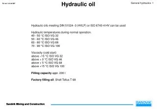
Hydraulic oil Hydraulic oils meeting DIN 51524--3 (HVLP) or ISO 6743-4 HV can be used Hydraulic temperatures during normal operation. 40 - 50 °C ISO VG 32 50 - 60 °C ISO VG 46 60 - 80 °C ISO VG 68 70 - 90 °C ISO VG 100 Viscosity (cold start) above –15 °C ISO VG 32 above + 0 °C ISO VG 46 above + 5 °C ISO VG 68 above +15 °C ISO VG 100 Filling capacity appr. 230 l Factory filling oil: Shell Tellus T 68
Hydraulic tank The machine is equipped with a 230 l hydraulic oil tank. Suction pipe and replaceable return filters for hydraulics and brake flushing are inside the tank. Two big sight glasses in the tank front make the checking of oil level easy. The oil level must be between the sight glasses when bucket is on ground and the oil is in normal temperature (over 60 °C) A drain hose with drain tap (6) is installed to the tank bottom tomake the oil draining easier and cleaner. To clean the oil tank the top cover (2) must be removed. 1. Tank breather 2. Hydraulic tank top cover 3. Sight glasses 4. Return oil filter Z307 5. Return oil filter Z308 6. Drain tap 7. Suction pipe
Filters state indication In three-module systems, there is one common input for all filters on the Middle module.When the input is activated, a warning appears on the display. There is an indicator light for each filter on the gauge panel in the machine. The indicator light shows which filter causes the alarm. Inputs Outputs
Functional description of Return filter The return filter cleans the hydraulic oil returning to the tank. Filtration capacity β10=75. The return filter is equipped with a magnetic filtration system. Magnetic filtration is effective on full flow, even during by-pass. Spring-loaded non-return valve (1.) Non--return valve allows the hydraulic oil returning to the tank past the filter when the pressure on the primary side of the filter is more than 1,4 bar greater than the pressure on the secondary side. If the hydraulic oil is cold, viscosity is higher and by--pass valve may open at lower pressure. Filter limit switch S377 (2.) Limit switch S377 indicates blockage of the filter.
Limit swithes + temperature sensor Limit switch S356 (3.) The limit switch indicates critical low level in the hydraulic oil tank. Limit switch S312 (4.) The limit switch indicates too low level in the hydraulic oil tank. Temperature sensor B301 (5.) The temperature sensor measures the temperature of the hydraulic oil. Filter limit switch S377 See page “Functional description of Return filter”
Suction lines Bleeding plug Suction lines consist of hoses, main suction pipe and suction connection. The main suction pipe leads the oil from bottom of the tank to the suction connection and forward to pumps through the hoses. Brake release pump unit and emergency steering pump unit (option) has separate suction pipes which are separately connected to the tank.
Pilot control pressure unit Pilot control pressure unit V306 Pilot control pressure unit contains valve block, pressure accumulator and follow-up valve. Pilot pressure valve block (1.) Pilot pressure valve block includes the following four components: Shuttle valve The shuttle valve directs the hydraulic pressure from inlet connections P1 and P2 to the pressure-reducing valve. Pressure relief valve The pressure reducing valve reduces Pilot control pressure unit outlet pressure to 35 bars. Non-return valve The non-return valve prevents hydraulic oil flow from the pilot control pressure line to pressure reducing valve. Follow--up valve Follow-up valve protects the pilot control circuit from too high pressure if the pressure-reducing valve is damaged. Pressure accumulator (2.) Pressure accumulator volume is 0,7 liter and the pre-charge pressure is 12 bars. When the external pressure in the line is more than 12 bars, accumulator charges, in other words stores hydraulic energy. If the external pressure falls in the line, the accumulator discharges and releases the hydraulic oil it has stored. Solenoid valve V315 (3.) Solenoid valve V315 drains the pressure accumulator when solenoid Y367 is de-energized.
Pressure measuring points 210 bar 210 bar 210 bar 210 bar
Pressure measuring points 220 bar 210 bar
Pressure measuring points 125 bar 210 bar
Pressure measuring points 230 bar 152-190 bar 117 bar 117 bar 1,5 bar 117 bar
Hydraulic oil coolers system description Pump P301.1 block 2 produces pressure to the oil coolers and air condition unit (option). Maximum pressure is limited to 210 bars by a pressure relief valve V317. There are two separate cooler sections in the cooler, one for hydraulic cooling and one for transmission cooling. From the pump oil flows through the air conditioning unit (optional) to the fan motors and hydraulic cooler. From the hydraulic cooler oil flows back to tank. If hydraulic oil flow to coolers suddenly stops and cooling fans rotation continues, oil circulates through the cooler motors until the motors stops. The hydraulic oil flow rotates the cooling fan, which produces air flow to cool the oil in the cooler. Pressure relief valve V317 The pressure relief valve V317 limits the hydraulic pressure going to the air condition unit (option) and hydraulic coolers to a maximum of 210 bar. Non-return valve Non-return valve prevents oil flow passing the cooler motors in normal working situation. If hydraulic oil flow suddenly stops and cooling fans rotation continues, non-return valve allows the hydraulic oil to circulates through the cooler motors until the motors stops.
Gear-type double pump P301.1 Double pump produces hydraulic pressure needed in the hydraulic systems. The pump has two blocks on the same shaft. The shaft speed is approximately 2270 rpm when the engine is running at 2150 rpm. The shaft rotates counter-clockwise. Block 1 Block 1 produces the hydraulic pressure needed for steering, pilot control and ejector function (optional). Maximum pressure is limited to 220 bars by a pressure relief valve. The volume flow is proportional to the engine rpm and the maximum flow is 92 l/min. The pump block outlet is equipped with a non-return valve, which prevents the hydraulic flow from returning to the pressure side of the pump block. Block 2 Block 2 produces the hydraulic pressure needed for air condition (optional) and oil cooler. Maximum pressure is limited to 210 bars by a pressure relief valve. The volume flow is proportional to the engine rpm and the maximum flow is 36 l/min. See the separate PGP620 service instructions manual in Toro Work Shop Manual for dismantling, assembly and inspection information.
Gear-type double pump P301.2 Double pump produces hydraulic pressure needed in the hydraulic systems. The pump has two blocks on the same shaft. The shaft speed is approximately 2270 rpm when the engine is running at 2150 rpm. The shaft rotates anti-clockwise. Block 1 Block 1 produces the hydraulic pressure and flow needed for boom and bucket hydraulics. Maximum pressure is limited to 210 bars by a pressure relief valve. The volume flow is proportional to the engine rpm and the maximum flow is 92 l/min. Block 2 Block 2 produces the hydraulic pressure and flow needed for the brake system and pilot control. Maximum pressure is limited to 230 bars by a pressure relief valve. The volume flow is proportional to the engine rpm and themaximum flow is 36 l/min. See the separate PGP620 service instructions manual in Toro Work Shop Manual for dismantling, assembly and inspection information.
Variable displacement type blower pump P302 Pump P302 is a piston pump. Shaft speed is 2300 rpm when the engine is running at 2150 rpm. Pump produces hydraulic pressure and flow needed for engine cooler. Maximum pressure is limited to 350 bars by a pressure relief valve. The volume flow produced by the pump is adjusted electrically according to the need of engine cooling capacity.
Starting new pumps 1. Make certain that the entire hydraulic system is clean. 2. Fill tank to proper level with recommended grade of hydraulic fluid. 3. Prime the suction lines and the variable displacement type pump case drain with hydraulic oil. 4. A new pump and system should not be started and immediately operated at full speed or pressure. The recommended procedure is to gradually speed up to approximately one--half operational speed or a minimum of 1000 R.P.M.. at minimum pressure. Preliminary circuit checks for air entrapment, leaks, etc., may be made at this time. When the recommended operation viscosity and temperature has been achieved, load may be alternatively applied up to the relief valve setting to check for satisfactory operation of all circuit components. See the separate pump manufacturers service instructions manual for dismantling, assembly and inspection information.
Checking and adjusting, Pilot pressure test General The hydraulic oil temperature should be 60...80 °C. Connect and disconnect pressure gauge(s) only when the circuit is not pressurized. Use only special couplings for pressure testing. Do not overtighten couplings. When special couplings are used, finger tight is adequate. Over tightening causes harmful leakage. Use hose(s) long enough to read the gauge(s) while sitting in the cabin. Pilot pressure test 1. Connect a pressure gauge to the quick-disconnect fitting. 2. Run the engine at low idle. 3. Pressure should be 35 bar (3.5 MPa). Only perform maintenance work when the machine is parked. Use the appropriate tools for the task. Replace or repair faulty tools and equipment. When performing maintenance and repair work, make sure there are no unauthorised persons in the working area.
Forced functions (requires service password) Forced functions windows are used for control the machine’s different functions by using the display module’s buttons instead of the machine’s control buttons. A forced functions window can replace a broken control actuator; for example, if the steering joystick is broken, the machine can be driven for service using a forced functions window. Test functions may cause unexpected movements of the machine. Always be sure when test functions is done there is no-one beside the machine and the machine has enough free space.
Forcing the digital outputs This window is used for forcing the digital outputs of each connector of a module on or off NOTE! The Dashboard and Rear modules’ connectors can select only if there are five modules in the machine: 1. On the module menu (I/O Force), select the connector of the module whose outputs you want to force. 2. Press the Ok button, the forcing window of the connector you selected opens. The connector pin values are shown according to their status when the window was opened. 3. Switch the output (or outputs) to be forced on or off. ”1” forces the output on, ”0”forces the output off. 4. Start the forcing by pressing and holding the SENDbutton. The forcing stays active until you release the button. NOTE! The SEND button forces all the digital outputs of the connector that has been selected to the status defined on the window.