Download
1 / 30
300 likes | 332 Vues
Explore the key modules on board, including NTSC camera, microcontroller, stepper motor specifications, DSP, and FPGA. Learn about the implementation, challenges, and software tasks in this real-time embedded system.

E N D
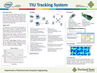
Color Discriminating Tracking System Lloyd Rochester Sam Duncan Ben Schulz Fernando Valentiner
Different Modules on Board • NTSC Camera with Co-Axial output. • PC104+ and PCI Frame Grabber. • 30 Frames/ Second at 640x280 resolution. • Will be completed in Real-Time embedded systems.
Microcontroller Board • HC11 • 2 serial inputs for PC104+ and PC. • NES Controller • LCD memory mapped, PIC controlled • Addressing interrupts
Motor circuit • Stepper motor controllers have full/half step mode for different accuracy, as well as a range of varying currents for different speeds. • Software control can converge smoothly on a target based on how many steps away. • Motors very noisy, inductors have huge voltage spikes when switching current. • Steppers will be on a different power circuit than microcontroller.
Stepper Motor Specifications • Limited by switching speeds of hardware controllers • Can sweep 30 degrees / step in full step mode,15 degrees / step in half step mode. • Travel full field of view ~1 second. • Torque curve sufficient for turret.
Digital Signal Processor: • Analog Blackfin or Tigershark DSP • Motorola 56307 – used in DSP lab • PC104 Pentium processor
PIC microcontroller • Pros: • Very easy to use. • Cons: • Everything done for us already.
MC68HC11 Specifications: • 8-channel A/D converter (may use external chip) • Asynchronous serial communications interface (SCI) • Separate synchronous serial peripherals interface (SPI) • 2 8-bit accumulators (A & B), which can act as a single 16-bit accumulator (D)
Specifications continued: • 3 input capture lines, 5 output capture lines • 2 16 bit index registers • 1 stack pointer
Memory: • Can address 64K memory. • Possibly have 32k EPROM, 32k SRAM
Expanded Mode: • Onboard memory will not be used. • Expanded mode will be enabled so HC11 reads from external memory.
FPGA • Xilinx Spartan FPGA XC4005E • Primary Function: Decode address for Memory Mapping
Optional use of FPGA: • Stepper motor controls • Nintendo controller logic • Interrupt servicing
On Board Demonstrations: • The controller will have a control mode that can be enabled to put the laser into demo mode. • 3 separate preprogrammed paths: Circle, Square, and Infinity.
The Motor System Problems • Accuracy • Control • Position / Calibration
Accuracy: • Bipolar stepper motors • 3.8 degree and 1.9 degree Industry Standard • H-Bridge controller required • Half step implementation realization
H-Bridge Controllers • 1 pin Step control • Pulse width for full or half step • 2 pin Phase control • Direction of motor • 2 pin Current control • Handles up to 1.5 amps • Only need 0.5 to 0.75 amps
Positioning • Manual control for calibration • Uses NES game pad • Memory for position reference • Non volatile memory too slow • Shaft encoders just too inaccurate
Software Task Perform by software in our design
Small Software state machine for the four modes • Manual or Game Pad mode • Demo mode • Tracking mode • Calibration mode The current mode will be displayed on the LCD screen
Control of the two RS-232 interfaces • Serial interface to the PC104+ to receive XY coordinates for tracking • Serial Interface to monitor computer, this is used by the BUFFALO monitor program
Human Interface Devices • LCD, it will be used for most of the output to the user • Serial Terminal, information can be transmitted to the terminal for debugging purposes • LED lights, Sound, etc.
Monitor program • The Motorola BUFFALO monitor program located locally on EEPROM
Goals for the project • Minimum:Implement one two-dimensional laser turret controlled by one Game Pad. • Goal: Implement one two-dimensional laser turret controlled either by Demo Mode, Tracking system or Game Pad. • Extension: Implement two two-dimensional laser turrets controlled by Demo Mode, Tracking System or two Game Pads. • Maximum: Replace the laser by a more extravagant device, i.e. dart gun, BB gun, missile, etc.)
Objective Timeline • CDR: Main Board Schematics Obtain Main board parts Motor board schematics Assemble microcontroller board Get processor running • Milestone 1: Obtain Motor Board Assemble Motor board Finish and test microcontroller hardware Implement Game Pad interface
Objective Timeline (Cont) • Milestone 2: Monitor program running Implement interface with motors Real Time Embedded system PC104+ module • Expo: Run Demo modes for the laser Receive XY and control laser Calibrate stepper motors for tracking