Ultrasonic Tracking System
Ultrasonic Tracking System. Group # 4 Bill Harris Sabie Pettengill Enrico Telemaque Eric Zweighaft. Introduction. What is our project? Pan and tilt implemented system tracking an ultrasonic beacon which sends a signal to 3 ultrasonic receivers, is carried around the room by a team member

Ultrasonic Tracking System
E N D
Presentation Transcript
Ultrasonic Tracking System Group # 4 Bill Harris Sabie Pettengill Enrico Telemaque Eric Zweighaft
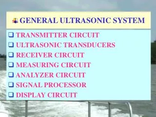
Introduction • What is our project? • Pan and tilt implemented system tracking an ultrasonic beacon which sends a signal to 3 ultrasonic receivers, is carried around the room by a team member • How does it work? • The signal coming from an ultrasonic transmitters is measured at three different locations • The difference in the time the signal is received at each sensor is used to calculate a distance relationship • Why is this project practical? • Mitsubishi Motor company uses a similar design in their automobiles for a collision avoidence system • Various pest and animal repellent systems use ultrasonic waves for tracking and repelling.
Objective • Simulation of pan & tilt system used as a cost efficient method to determine: • Motor required to drive system • Gear, belt and pulley combination needed • Response of system to motor, gear, belt and pulley • Maximum performance variables for system • Rough estimate of system response to sample payload • Chance to show that we were paying attention in all those math classes
Specifications • The system will track objects between 2 and 10 meters from the array • The system will track objects between 0 and 2 meters off the ground • The system will track items within .5 degree of accuracy (within 10 cms of the object with beacon) • The system must be able to track the beacon at the speed of a human walking (.64 rad/sec)
Major Change in Design • With our previous sensor structure, there was not a large enough motor that could handle the torque • We decided make a more compact sensor structure which allowed us to go with a much smaller motor in the Pittman 8000 series. • The sensor structure was made L shaped instead of T shaped to allow for a simpler timer circuit
Motor • Pittman GM8724S017 • 19.5:1 internal gearing ratio • Encoder mounted directly to rotor increases accuracy of encoder (encoder is not geared down) • External transmission gives additional reduction ratio of 3:1
Motor • Pittman GM8724S017 • Larger gearing ratio does not allow us to meet our speed requirements • Smaller gearing ratio does not allow us to meet our torque requirements • Gains must be chosen carefully to remain inside the feasible range for both speed and torque
Motor • Simulation • Sinusoidal input • Frequency of 0.63 rad/s
Motor • Speed vs. Torque plot • Shows that motor is well within limits, as long as gains are kept at reasonable levels
Controller • By intuitive adjustment of gains, a reasonable response was obtained • But “guessing” is not a valid design approach
Controller • SISO Design tool was used • Linearized model was obtained using the linearlization routines provided • Alternatively, the “linmod” command could be called to create a linear State Space model from the Simulink Diagram • This allows the designer to view pole/zero locations, bode plots, AND response plots all at the same time, and adjust poles, zeros, and gains in any of these formats
Controller SISO Window Step Response Overshoot is very undesirable
Controller SISO Window Step Response PM = 98.2° GM = Inf. Zero overshoot, 1% ess
Notes on Controller • Because of assumptions made in order to linearize the system, this controller does not perform perfectly on the non-linearized model, so some adjustments will have to be made during assembly and testing • We may wish to add an Integral term later to cancel the 1% overshoot • Does not seem necessary now- it would only hurt our transient response, and require more torque and speed from the motor
Justification for Sensor Parts • Given the cost of larger motors, needed to have a design with a small moment of inertia • The higher the clock frequency of timer circuit, the smaller our sensor structure has to be • The cheapest TTL components had a maximum functional frequency of 5 MHz • Chose an oscillator accordingly
Cost Pan and Tilt Parts Total $478.64
Additional Costs Total Amount for Timing Circuit and Sensors: $46.52 Total Cost for project: $533.84
February Week2 Week3 Week 4 Placing parts and payload on CAD drawings to calculate P,I,M values for Matlab simulation (Bill, Sabie) Hardware - CAD designed payload added to Ben’s CAD drawings system and edited P,I,M values are calculated (Eric, Sabie) Final design specifications are met (All members) Parts are ordered (Eric, Sabie) Hardware Simulation of pan and tilt system to obtain feasibility and performance of test motor with a test payload (Bill) Final Motor feasibility simulation with payload on pan and tilt system (Bill, Enrico) Testing of control system’s ability to track a signal using amplitude, or distance and time measurements (All members) Software Reports Presentation writeup (Enrico Eric) Proposal writeup (Sabie, Enrico) TBD
March Weeks1-2 Week3 Week4 Sensor development with focus on time\distance relationship (Eric, Sabie) Encoder and amplifier properties researched (Bill, Enrico) Design model assembled (Enrico, Sabie) Sensor assembly (Bill, Eric) Further tolerance testing of physical equipment Hardware Current Feedback control analyzing and testing to find proper gains for accurate tracking (Bill, Enrico) Encoder and amplifier properties simulated (Eric, Sabie) Testing and fine tuning of control feedback system (Bill, Sabie) Sensor testing with system (Enrico, Eric) Test mechanics of system in terms of motion (Bill, Enrico) Test mechanics of system in terms of tracking (Eric, Sabie) Software Reports Progress Report (All members) TBD TBD