Download
1 / 10
140 likes | 530 Vues
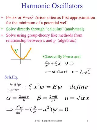
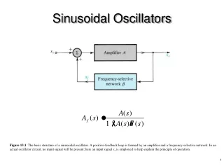
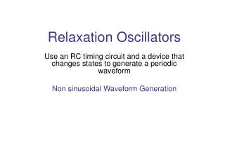
Relaxation Oscillators. Use an RC timing circuit and a device that changes states to generate a periodic waveform Non sinusoidal Waveform Generation. A Triangular Wave Oscillator.

E N D
Relaxation Oscillators Use an RC timing circuit and a device that changes states to generate a periodic waveform Non sinusoidal Waveform Generation
A Triangular Wave Oscillator Positive and Negative going ramps are generated when the dual polarity switch is thrown back and forth at fixed intervals. This creates the shape of a triangular waveform Basic Triangular Wave Oscillator
Practical Triangular Wave Oscillator • Output of Comparator circuit is a square wave having constant positive and negative levels. • Square wave at the input (inverting) generates triangular wave at the output of Integrator circuit. • UTP (Upper Trigger Point) and LTP (Lower Trigger Point) determine the time of switching for comparator • More than one output periodic waveforms are present in the circuit and hence the name Function Generator is also applicable for this circuit
The amplitude of the square wave is set by the output swing of the comparator R2 and R3 set the amplitude of the triangular wave by establishing UTP and LTP voltages +Vmax and –Vmax levels are equal The frequency of both waveforms depends on R1 C time constant as well as the amplitude setting resistors,R2 and R3
By varying R1 ,the frequency of oscillation can be adjusted without changing the output amplitude
Sawtooth Voltage Controlled Oscillator (VCO) • VCO is a relaxation oscillator whose frequency can be changed by a variable dc control voltage. • VCO can be either sinusoidal or non sinusoidal. • PUT>>(Programmable Unijunction Transistor) terminates each ramp at a prescribed level and effectively reset the circuit.
PUT is a programmable uni junction transistor with an anode, a cathode, and a gate terminal. • The gate is always biased positively with respect to the cathode. • When the anode voltage exceeds the gate voltage by approximately 0.7 V, the PUT turns on and acts as a forward-biased diode. • When the anode voltage falls below this level the PUT turns off. • Also, the current must be above the holding value to maintain conduction. • The circuit operates as a regular integrator when the negative input dc voltage –VIN is applied • The PUT triggers on when the output ramp (at the anode) • exceeds the gate voltage by 0.7 V • The gate is set to the approximate desired sawtooth peak volt- • age. • When the PUT turns on, the capacitor rapidly discharges. • The capacitor does not discharge completely to zero because of the PUT's forward voltage. V F .
Discharge continues until the PUT current falls below the holding value. • At this point, the PUT turns off and the capacitor begins to charge again, thus generating a new output ramp. • The sawtooth amplitude and period can be adjusted by varying the PUT gate voltage. • The frequency of oscillation is determined by the RiC time constant of the integrator and the peak voltage set by the PUT. • The time it takes a capacitor to charge from VF to Vp is the period, T, of the sawtooth waveform (neglecting the rapid discharge time).
A Square-Wave Oscillator The Op-amp's inverting input is the capacitor voltage VC The non inverting input is a portion of the output fed back through resistors R2 and R3 Let initially the capacitor be uncharged, and thus the inverting input is at 0 V. This makes the output a positive maximum The capacitor begins to charge toward Vout through R1 When VC equals Vf , the op-amp switches to the maximum negative state. The operation of this oscillator is based on charging and discharging of a capacitor, so it is a relaxation oscillator
At this point, the capacitor begins to discharge from + Vf towards –Vf When the capacitor voltage reaches – Vf , the op-amp switches back to the maximum positive state.