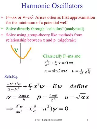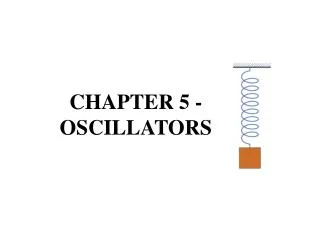
OSCILLATORS
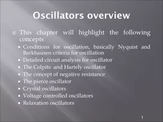
OSCILLATORS. OBJECTIVES :. Understand sinusoidal oscillator circuits and state their characteristics. Know types of sinusoidal oscillator. INTRODUCTION. The basic signal-generating source for various applications in electronic circuits is 'oscillator'.


OSCILLATORS
E N D
Presentation Transcript
OBJECTIVES : Understand sinusoidal oscillator circuits and state their characteristics. Know types of sinusoidal oscillator
INTRODUCTION The basic signal-generating source for various applications in electronic circuits is 'oscillator'. It will change the dc to an ac signal and can generate any frequency required by the circuit.
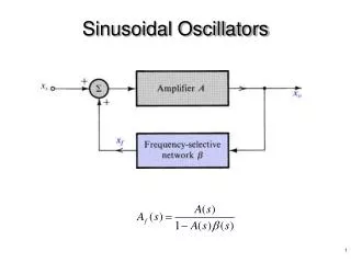
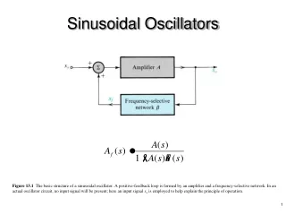
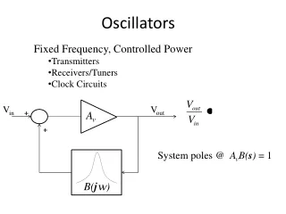
2.1 Understand sinusoidal oscillator circuits and state their characteristics Block Diagram Of an oscillator • Oscillators are devices that convert DC voltage into ac voltage without any external source at a particular frequency
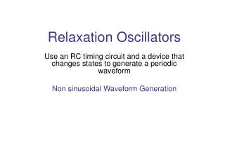
Harmonic & Non-Harmonic An Oscillators There are two types of an oscillators:i. Harmonic oscillator - the sine wave.ii. Non-harmonic oscillator - in the fourth wave, triangle wave, etc.. Nowadays, Non- harmonic oscillator become important due to digital circuit mostly used in electrical equipment and the circuits required timer device for the timing.
REQUIREMENT OF AN OSCILLATOR CIRCUITS The basic oscillator circuit consists of : i. Amplifierii. Feedbackiii. Frequency generation circuit. Block diagram of an oscillator 1) Amplifier An “oscillator” is device that produces oscillations (back-and –forth) charges-usually an electronic circuit that produces AC-from a steady (DC) source of power. The amplifier circuit requires a DC power supply source to bias the transistor.
REQUIREMENT OF AN OSCILLATOR CIRCUITS-contd 2) Feedback Feedback is a condition in which part of the output signal supplied to the input. When the oscillator has no input signal, the feedback signal is the input signal for the amplifier in the oscillator circuit. There are two principles of the feedback, negative feedback and positive feedback. Oscillators using the principle of positive feedback. Figure 2.1.2a shows the basic block diagram of a feedback system:
REQUIREMENT OF AN OSCILLATOR CIRCUITS-contd 3) Frequency generation circuit Feedback signal and the amplifier can not be sure of the swing, it requires the control / frequency generation and it usually placed in the feedback.The frequency generation circuit of the oscillator in the consumer products can divided into: i. Oscillator that generates audio frequency RC Oscillator Network (Resistance-Capacitor). It is to produce medium and low frequency signals.Examples of types of RC oscillator is the oscillator phase shift and Wein bridge oscillator.ii. Oscillator that generates radio frequency: The oscillator LC network (inductor-capacitor). . It is to produce high frequency signals (> 1MHz), and often it produces a stable frequency.Examples of the type LC oscillator is Armstrong Oscillator, Colpitts, Hartley and Crystal.
Basic LC Oscillator Tank Circuit The circuit consists of an inductive coil, L and a capacitor, C. The capacitor stores energy in the form of an electrostatic field and which produces a potential (static voltage) across its plates, while the inductive coil stores its energy in the form of an electromagnetic field. The capacitor is charged up to the DC supply voltage, V by putting the switch in position A. When the capacitor is fully charged the switch changes to position B. The charged capacitor is now connected in parallel across the inductive coil so the capacitor begins to discharge itself through the coil. The voltage across C starts falling as the current through the coil begins to rise. This rising current sets up an electromagnetic field around the coil which resists this flow of current. When the capacitor, C is completely discharged the energy that was originally stored in the capacitor, C as an electrostatic field is now stored in the inductive coil, L as an electromagnetic field around the coils windings.
Basic LC Oscillator Tank Circuit As there is now no external voltage in the circuit to maintain the current within the coil, it starts to fall as the electromagnetic field begins to collapse. A back emf is induced in the coil (e = -Ldi/dt) keeping the current flowing in the original direction. This current now charges up the capacitor, C with the opposite polarity to its original charge. C continues to charge up until the current reduces to zero and the electromagnetic field of the coil has collapsed completely. The energy originally introduced into the circuit through the switch, has been returned to the capacitor which again has an electrostatic voltage potential across it, although it is now of the opposite polarity. The capacitor now starts to discharge again back through the coil and the whole process is repeated. The polarity of the voltage changes as the energy is passed back and forth between the capacitor and inductor producing an AC type sinusoidal voltage and current waveform. This then forms the basis of an LC oscillators tank circuit and theoretically this cycling back and forth will continue indefinitely. However, every time energy is transferred from C to L or from L to C losses occur which decay the oscillations
Resonant Frequency of a LC Oscillator The frequency of the oscillatory voltage depends upon the value of the inductance and capacitance in the LC tank circuit. For resonance to occur in the tank circuit, there must be a frequency point were the value of XC, the capacitive reactance is the same as the value of XL, the inductive reactance (XL = XC). Where: • L is the Inductance in Henries • C is the Capacitance in Farads • ƒr is the Output Frequency in Hertz
2.2 Types of Sinusoidal oscillator2.2.1a Amstrong Oscillator Resistors R1, R2 and R3 are provided bias voltage to the transistor. Capacitors C1 and C2 are avoid the alternating signal. The transformer Tr is to produce a phase shift of 180o to get a feedback voltage in phase with the input transistors.
2.2.1a Amstrong Oscillator-contd The ratio between the coil windings L1 to L2 coils is the product of the gain, A, with the feedback factor, , is a (| A | = 1). Example 1 if the amplifier gain is 10, the ratio of windings must be1: 10.A = 10 x 0.1 = 1
2.2.1(a) Amstrong Oscillator: Frequency of Oscillation Oscillation frequency is determined by the circuit L2.C2 given by: The ratio between the transformer windings is 1:10 and capacitors used in the resonant circuit is 50 F Get the resonance frequency for this circuit.
2.2.1b Colpitts oscillator 2.1.1(b) Circuit Connection of Colpitts oscillator: Colpitts oscillator using two capacitors and an inductor in the frequency generation circuit Figure 2.1.1b: Colpitts oscillator
2.2.1b Colpitts oscillator:operation Transistors and resistors R1, R2, R3 and R4 are a combination of amplifier circuits. Capacitors C3 and C4 are used to overtake the signal s shuttle to earth. The amplifier will provide different phase of the output signal 180o. The LC circuit in the feedback loop are produced a phase shift of 180o. Therefore, the feedback voltage will be in phase with the input voltage on the transistor.
2.2.1b Colpitts oscillator-contd Frequency of Oscillation: Oscillation frequency is determined by the circuit LC given by: The capacitor in above circuit is connected in series
2.2.1c Hartley oscillator 2.1.1(c) Circuit Connection of Hartley oscillator: • Hartley oscillator using two inductors and a capacitor in the frequency generation circuit
2.2.1c Hartley oscillator-contd Frequency of Oscillation: Oscillation frequency is determined by the circuit LC given by: The inductors in above circuit is connected in series 19
2.1.1(d) Crystal Oscillator: Oscillator is the most stable and precisely when using a piezoelectric crystal in a feedback circuit. When the alternating voltage is applied to the crystal produced the mechanical vibrations. These vibrations has the natural resonant frequencies are depend on the thickness of the crystal (The high frequency, the thinner of the crystal). Figure 2.1.1d Electric Circuits connection Symbol Figure
2.1.1(d) Crystal Oscillator:contd Referring to the figure 2.1.1 d: Lh: The equivalent electric of the crystals mass Ch: The elasticity of crystals Rh: The friction resistance in the crystal structure Cm: The capacitance capacitor containers loaded crystals *The f1 generated by the series circuit Rh-LH-Ch. f2 components of the same series reaktan, Cm. z Parallel resonant Series resonant f f1 f2
2.1.1(d) Crystal Oscillator:CIRCUIT Frequency of Oscillation: Series resonance : Parallel resonance: Figure 2.1.1 (d): Crystal Oscillator
2.1.1e OSCILLATOR PHASE SHIFT (RC): Phase shift oscillator consists of amplifier and feedback network with three RC circuits (as shown in Figure 2.1.1e): Circuit connection of the Phase Shift Oscillator: Circuit Operation:The output signal from the amplifier of 180o out of phase with the input signal. For a positive feedback signal, the output signal phase shifted by 180o, so that to be in phase with the input. RC network produces a phase shift of 180o
Phase-shift oscillator. The amount of actual phase shift in the circuit depends upon the values of the resistor and the capacitor, and the chosen frequency of oscillations with the phase angle ( Φ ) being given as:
2.1.1e OSCILLATOR PHASE SHIFT (RC): Frequency of Oscillation: • If all the resistors, R and the capacitors, C in the phase shift network are equal in value, then the frequency of oscillations produced by the RC oscillator is given as:
Example • Determine the frequency of oscillations of a RC Oscillator circuit having 3-stages each with a resistor and capacitor of equal values. R = 10kΩ and C = 500pF Answer: