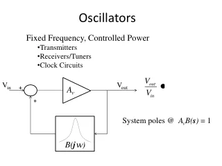
Oscillators
Oscillators. Oscillators with LC Feedback Circuits. Oscillators. Oscillators With LC Feedback Circuits. For frequencies above 1 MHz, LC feedback oscillators are used. LC feedback oscillators use resonant circuits in the feedback path.


Oscillators
E N D
Presentation Transcript
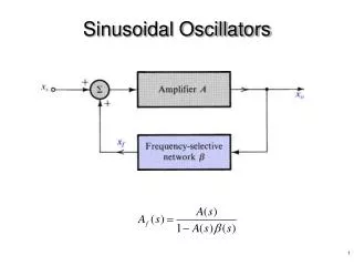
Oscillators Oscillators with LC Feedback Circuits
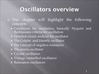
Oscillators Oscillators With LC Feedback Circuits • For frequencies above 1 MHz, LC feedback oscillators are used. • LC feedback oscillators use resonant circuits in the feedback path. • We will discuss the Colpitts, Hartley and crystal-controlled oscillators. • Transistors are used as the active device in these types.
LC Oscillators – Colpitts The Colpitts oscillator utilizes a tank circuit (LC) in the feedback loop to provide the necessary phase shift and to act as a resonant filter that passes only the desired frequency of oscillation.
LC Oscillators – Colpitts A popular LC oscillator is the Colpitts oscillator. It uses two series capacitors in the resonant circuit. The feedback voltage is developed across C1. The effect is that the tank circuit is “tapped”. Usually C1 is the larger capacitor because it develops the smaller voltage.
LC Oscillators – Colpitts The resonant frequency can be determined by the formula below.
LC Oscillators – Colpitts • Figure below shows the input impedance of the amplifier acts as a load on the resonant feedback circuit and reduces the Q of the circuit. • The resonant frequency of a parallel resonant circuit depends on the Q, according to the formula below:
LC Oscillators – Hartley The Hartley oscillator is similar to the Colpitts except that the feedback circuit consists of two series inductors and a parallel capacitor.
LC Oscillators – Hartley The frequency of oscillation for Q > 10 is: where LT = L1 + L2 One advantage of a Hartley oscillator is that it can be tuned by using a variable capacitor in the resonant circuit.
LC Oscillators – Crystal-Controlled The crystal-controlled oscillator is the most stable and accurate of all oscillators. A crystal has a natural frequency of resonance. Quartz material can be cut or shaped to have a certain frequency.
LC Oscillators – Crystal-Controlled Since crystal has natural resonant frequencies of 20 MHz or less, generation of higher frequencies is attained by operating the crystal in what is called the overtone mode
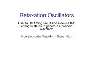
Oscillators Relaxation Oscillators
Oscillators – Relaxation Relaxation oscillators make use of an RC timing and a device that changes states to generate a periodic waveform (non-sinusoidal). 1. Triangular-wave 2. Square-wave 3. Sawtooth
Oscillators – Relaxation Triangular-wave oscillator Triangular-wave oscillator circuit is a combination of a comparator and integrator circuit. A square wave can be taken as an output here.
Oscillators – Relaxation Triangular-wave oscillator • Assume that the output voltage of the comparator is at its maximum negative level. • This output is connected to the inverting input of the integrator through R1, producing a positive-going ramp on the output of the integrator. • When the ramp voltage reaches the UTP, the comparator switches to its maximum positive level. • This positive level causes the integrator ramp to change to a negative-going direction. • The ramp continues in this direction until the LTP of the comparator is reached and the cycle repeats.
Oscillators – Relaxation Triangular-wave oscillator
Oscillators – Relaxation Triangular-wave oscillator Amplitude of the triangular output is set by establishing the UTP and LTP voltages according to the following formulas: The frequency of both waveforms depends on the R1C time constant as well as the amplitude-setting resistors, R2 and R3. By varying R1, the fr can be adjusted without changing the output amplitude.
Oscillators –Relaxation - EXAMPLE Determine the frequency of oscillation of the circuit in figure below. To what value must R1 be changed to make the frequency 20 kHz? Answer: fr = 8.25 kHz, R1 = 4.13 kOhm
Oscillators – Square-wave A square wave relaxation oscillator is like the Schmitt trigger or Comparator circuit. The charging and discharging of the capacitor cause the op-amp to switch states rapidly and produce a square wave. The RC time constant determines the frequency.
Oscillators – Sawtooth voltage controlled oscillator (VCO) Sawtooth VCO circuit is a combination of a Programmable Unijunction Transistor (PUT) and integrator circuit.
Oscillators – Sawtooth VCO OPERATION • Initially, dc input = VIN • Vout = 0V, Vanode < VG • The circuit is like an integrator. • Capacitor is charging. • Output is increasing positive going ramp.
Oscillators – Sawtooth VCO OPERATION
Oscillators – Sawtooth VCO OPERATION • When Vout = VP • Vanode > VG , PUT turns ‘ON’ • The capacitor rapidly discharges. • Vout drop until Vout = VF. • Vanode < VG, PUT turns ‘OFF’ VP – maximum peak value VF – minimum peak value
Oscillators – Sawtooth VCO OPERATION Oscillation frequency
Oscillators – Sawtooth VCO EXAMPLE In the following circuit, letVF = 1V. a) Find; (i) amplitude; (ii) frequency; b) Sketch the output waveform
Oscillators – Sawtooth VCO EXAMPLE (cont’d)
Oscillators – Sawtooth VCO EXAMPLE – Solution a) (i) Amplitude and So, the peak-to-peak amplitude is;
Oscillators – Sawtooth VCO EXAMPLE – Solution a) (ii) Frequency
Oscillators – Sawtooth VCO EXAMPLE – Solution a) (ii) Frequency
Oscillators – Sawtooth VCO EXAMPLE – Solution b) Output waveform
Oscillators The 555 timer as an oscillator
Oscillators The 555 Timer As An Oscillator The 555 timer is an integrated circuit that can be used in many applications. The frequency of output is determined by the external components R1, R2, and C. The formula below shows the relationship.
Oscillators The 555 Timer As An Oscillator Duty cycles can be adjusted by values of R1 and R2. The duty cycle is limited to 50% with this arrangement. To have duty cycles less than 50%, a diode is placed across R2. The two formulas show the relationship; Duty Cycle > 50 %
Oscillators The 555 Timer As An Oscillator Duty Cycle < 50 %
Oscillators The 555 Timer As An Oscillator
Oscillators The 555 Timer As An Oscillator The 555 timer may be operated as a VCO with a control voltage applied to the CONT input (pin 5).