Oscillators
Learn about the functionality and applications of oscillators, circuits that generate periodic signals without external input. Explore different types, design criteria, and practical considerations for oscillation in electronic systems.


Oscillators
E N D
Presentation Transcript
Oscillators Presented by Dr.SAROAJ ADAK Professor DEPARTMENT OF ELECTRONICS AND COMMUNICATION ENGINEERING VISAKHA INSTITUTE OF ENGINEERING & TECHNOLOGY
Introduction • Oscillator is an electronic circuit that generates a periodic waveform on its output without an external signal source. It is used to convert dc to ac. • Oscillators are circuits that produce a continuous signal of some type without the need of an input. • These signals serve a variety of purposes. • Communications systems, digital systems (including computers), and test equipment make use of oscillators
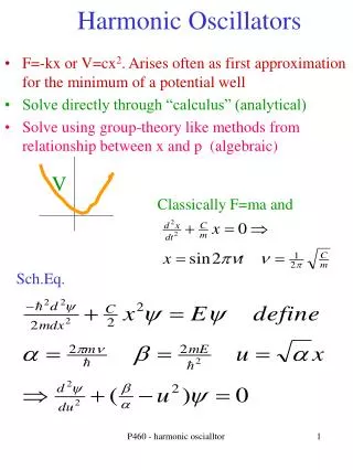
Oscillators Oscillation: an effect that repeatedly and regularly fluctuates about the mean value Oscillator: circuit that produces oscillation Characteristics: wave-shape, frequency, amplitude, distortion, stability EE3110 Oscillator
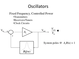
Application of Oscillators • Oscillators are used to generate signals, e.g. • Used as a local oscillator to transform the RF signals to IF signals in a receiver; • Used to generate RF carrier in a transmitter • Used to generate clocks in digital systems; • Used as sweep circuits in TV sets and CRO. EE3110 Oscillator
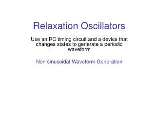
Oscillators • Oscillators are circuits that generate periodic signals • An oscillator converts DC power from the power supply into AC signal power spontaneously - without the need for an AC input source Figure 9.67 Repetitive ramp waveform.
Introduction • An oscillator is a circuit that produces a repetitive signal from a dc voltage. • The feedback oscillator relies on a positive feedback of the output to maintain the oscillations. • The relaxation oscillator makes use of an RC timing circuit to generate a nonsinusoidal signal such as square wave Sine wave Square wave Sawtooth wave
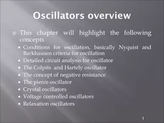
Types of oscillators • RC oscillators • Wien Bridge • Phase-Shift • LC oscillators • Hartley • Colpitts • Crystal • Unijunction / relaxation oscillators
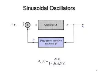
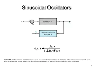
Linear Oscillators Figure 9.68 A linear oscillator is formed by connecting an amplifier and a feedback network in a loop.
Integrant of Linear Oscillators For sinusoidal input is connected “Linear” because the output is approximately sinusoidal A linear oscillator contains: - a frequency selection feedback network - an amplifier to maintain the loop gain at unity EE3110 Oscillator
Basic Linear Oscillator and If Vs = 0, the only way that Vo can be nonzero is that loop gain A=1 which implies that (Barkhausen Criterion) EE3110 Oscillator
Basic principles for oscillation • An oscillator is an amplifier with positive feedback.
Basic principles for oscillation • The closed loop gain is:
Basic principles for oscillation • In general A and are functions of frequency and thus may be written as; is known as loop gain
Basic principles for oscillation • Writing the loop gain becomes; • Replacing s with j • and
Basic principles for oscillation • At a specific frequency f0 • At this frequency, the closed loop gain; will be infinite, i.e. the circuit will have finite output for zero input signal - oscillation
Basic principles for oscillation • Thus, the condition for sinusoidal oscillation of frequency f0 is; • This is known as Barkhausen criterion. • The frequency of oscillation is solely determined by the phase characteristic of the feedback loop – the loop oscillates at the frequency for which the phase is zero.
Barkhausen Criterion – another way Figure 9.69 Linear oscillator with external signal Xin injected.
How does the oscillation get started? • Noise signals and the transients associated with the circuit turning on provide the initial source signal that initiate the oscillation
Practical Design Considerations • Usually, oscillators are designed so that the loop gain magnitude is slightly higher than unity at the desired frequency of oscillation • This is done because if we designed for unity loop gain magnitude a slight reduction in gain would result in oscillations that die to zero • The drawback is that the oscillation will be slightly distorted (the higher gain results in oscillation that grows up to the point that will be clipped)
Basic principles for oscillation • The feedback oscillator is widely used for generation of sine wave signals. • The positive (in phase) feedback arrangement maintains the oscillations. • The feedback gain must be kept to unity to keep the output from distorting.
Design Criteria for Oscillators • The magnitude of the loop gain must be unity or slightly larger – Barkhaussen criterion • Total phase shift, of the loop gain mus t be Nx360° where N=0, 1, 2, …
RC Oscillators • RC feedback oscillators are generally limited to frequencies of 1 MHz or less. • The types of RC oscillators that we will discuss are the Wien-bridge and the phase-shift
Wien-bridge Oscillator • It is a low frequency oscillator which ranges from a few kHz to 1 MHz.
Another way Figure 9.70 Typical linear oscillator.
Wien-bridge Oscillator • The loop gain for the oscillator is; • where; • and;
Wien-bridge Oscillator • Hence; • Substituting for s; • For oscillation frequency f0
Wien-bridge Oscillator • Since at the frequency of oscillation, T(j) must be real (for zero phase condition), the imaginary component must be zero; • which gives us – [how?! – do it now]
Wien-bridge Oscillator • From the previous eq. (for oscillation frequency f0), • the magnitude condition is; To ensure oscillation, the ratio R2/R1 must be slightly greater than 2.
Wien-bridge Oscillator • With the ratio; • then; K = 3 ensures the loop gain of unity – oscillation • K > 3 : growing oscillations • K < 3 : decreasing oscillations
Wien-Bridge Oscillator – another way Wien-bridge oscillator.
Wien-Bridge oscillator output Figure 9.75 Example of output voltage of the oscillator.
Wien Bridge Oscillator Frequency Selection Network Let and Therefore, the feedback factor, EE3110 Oscillator
can be rewritten as: For Barkhausen Criterion, imaginary part = 0, i.e., Supposing, R1=R2=R and XC1= XC2=XC, EE3110 Oscillator
Example By setting , we get Imaginary part = 0 and Due to Barkhausen Criterion, Loop gain Av=1 where Av : Gain of the amplifier Wien Bridge Oscillator Therefore, EE3110 Oscillator
Phase-Shift Oscillator • The phase shift oscillator utilizes three RC circuits to provide 180º phase shift that when coupled with the 180º of the op-amp itself provides the necessary feedback to sustain oscillations. • The gain must be at least 29 to maintain the oscillations. • The frequency of resonance for the this type is similar to any RC circuit oscillator:
Phase-Shift Oscillator R2 C R C v2 C v2 v3 v1 vi v1 vo R R
Phase-Shift Oscillator • Loop gain, T(s): • Set s=jw
Phase-Shift Oscillator • To satisfy condition T(jwo)=1, real component must be zero since the numerator is purely imaginary. • the oscillation frequency: • Apply wo in equation: • To satisfy condition T(jwo)=1 The gain greater than 8, the circuit will spontaneously begin oscillating & sustain oscillations
Phase-Shift Oscillator The gain must be at least 29 to maintain the oscillations
LC Oscillators • Use transistors and LC tuned circuits or crystals in their feedback network. • For hundreds of kHz to hundreds of MHz frequency range. • Examine Colpitts, Hartley and crystal oscillator.
Colpitts Oscillator • The Colpitts oscillator is a type of oscillator that uses an LC circuit in the feed-back loop. • The feedback network is made up of a pair of tappedcapacitors(C1 and C2)andan inductor Lto produce a feedback necessary for oscillations. • The output voltage is developed across C1. • The feedback voltage is developed across C2.
Colpitts Oscillator • KCL at the output node: • voltage divider produces: • substitute eq(2) into eq(1): - Eq (1) - Eq (2)
Colpitts Oscillator • Assume that oscillation has started, then Vo≠0 • Let s=jω • both real & imaginary component must be zero • Imaginary component: - Eq (3)
Colpitts Oscillator • both real & imaginary component must be zero • Imaginary component: • Combining Eq(3) and Eq(4): • to initiate oscillations spontaneously: - Eq (4)
Hartley Oscillator • The Hartley oscillator is almost identical to the Colpitts oscillator. • The primary difference is that the feedback network of the Hartley oscillator uses tappedinductors (L1 and L2)anda single capacitor C.
Hartley Oscillator • the analysis of Hartley oscillator is identical to that Colpitts oscillator. • the frequency of oscillation: