Oscillators
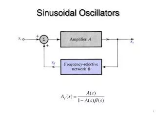
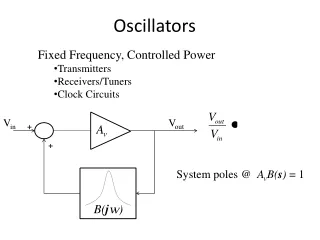
Fixed Frequency, Controlled Power Transmitters Receivers/Tuners Clock Circuits. Oscillators. V in. V out. +. A v. +. System poles @ A v B( s ) = 1. B( j w ). Barkhausen Criteria. System poles @ A v B( s ) = 1. w 0.


Oscillators
E N D
Presentation Transcript
Fixed Frequency, Controlled Power • Transmitters • Receivers/Tuners • Clock Circuits Oscillators Vin Vout + Av + System poles @ AvB(s) = 1 B(jw)
Barkhausen Criteria System poles @ AvB(s) = 1 w0 Pole in RHP: Oscillation amplitude grows until amplifier starts to clip, then Av’ < Av. Root locus for Av’ < Av
Oscillator Design Vin Vout + Av + B(jw) Common Base: rin = re Av = Rc’/re Common Emitter: rin = (b+1)re Av = -Rc’/re Frequency Selective Feedback Network LC Network Quartz Crystal
Amplifier Gain • Av = + Rc’/re • re = 26 mV/IE (from DC Analysis) • Rc’ : Parallel Combination of • Transformed Load: RL’ = RL/av2 • Parasitic Loading (finite Q): Rcoil = QuXT • Feedback Network: Re’ = . . . . . • Collector Dynamic (AC) Resistance: rc~ 20 k • Any other resistances in Collector Circuit
Hartley Oscillator(common base, autotransformer feedback) C E
Hartley Oscillator VCC + - VCC C IC= b IB R1 LT , Qu b , rc IB B n1 CT DC Equivalent IE= (b+1) IB R1 n2 n3 RL E R2 re R3 R2 R4 BP R3 BP AC Equivalent R4 E C ie n2 + ve - rc re R3 n1 B
B1vc R4 ve = B1B2vc E C + vc - ie n2 + ve - rc RP re R3 n1 B Ideal B=B1B2 ve = Bvc E C + vc - ie + ve - rc RP re R3 B
ve = Bvc E + vc - C ie + ve - rc RP re B ve = Bvc Note: any additional resistance placed across the tank circuit must be included as an additional parallel contribution. B B E C + vc - ie + ve - re B
Barkhausen: is AVB > 1 ? Book Example : f = 1 Mhz IC~ IE= 1 ma n1= 10, n2= 100, n3= 5 (subscripts changed) LT = 53 uH, Qu = 50, XT = 333 W RL= 50 W R3 = 1 k W R4= 0 W (therefore, B2 = 1) rc = 50 k W AV VCC LT , Qu b , rc B n1 CT R1 n2 n3 RL re R2 R4 BP R3 BP
Maximum Power Considerations The maximum 0-pk collector AC voltage is: The maximum power to the load is: VCC was not given for this problem, but we can determine a minimum value required to prevent saturation at max power by recalling that . . .