Signalling
Philip Meurant. Signalling. This presentation will cover. A brief history of Signalling in NSW Very basic principles The different types of Interlocking Systems in Use Control Systems Signal interpretation. Signalling: A brief History. 1855: Railway line in Sydney opened

Signalling
E N D
Presentation Transcript
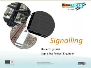
Philip Meurant Signalling
This presentation will cover A brief history of Signalling in NSW Very basic principles The different types of Interlocking Systems in Use Control Systems Signal interpretation
Signalling: A brief History 1855: Railway line in Sydney opened Initial application of token working, then time table working until 1879. 1877: A campaign for a safeworking system was passed 1878: Emu Plains collision occurred just before the new system introduced 1879: Manual Block Instruments introduced 1881: First mechanical interlocking frame at Burwood 1888: Electric tablet 1891: Electric train staff 1910: Power Signalling introduced 1913: Double light system 1915: 3 position upper quadrant signalling 1924: Colour Light signals 1928: All electric miniature lever frame
Signalling: BasicPrinciples • Track Circuits: Identify the location of trains. • Interlocking: Prevents conflicting train movements, ensures locking of signals and points. • Signals: Visually displays information to train drivers. • Train Stop: Operates in association with signals to prevent trains overrunning an authority. • Points: Diverts trains at junctions or yards. • Signal Box / Control Centre: Operates the train movements.
Track Circuits Track circuits are used to locate trains in the system. Information is feed from the track relay to vital control circuits and/or to the Interlocking to provide train protection and locking. A basic track circuit shown below is made up of the following components:- • A power source • A variable resistance • A relay • Insulated rail joints to separate rail sections
Interlocking What is an Interlocking? In general terms an interlocking is a location where plain track ends and trackwork with points and crossings complicate train movements. These areas are likely to be:- • Junctions where two or more main lines meet. • Complex yards or sidings are encountered. These may be at larger towns or depot facilities. An interlocking provides for complex train movements and shunting of trains. It provides for the protection of multiple train movements within a localised area. So the next question is how do you do that?
Interlocking cont Mechanical • Very early mechanical interlockings consisted of large levers, pulleys, steel wire to control signals and channel iron (roding) to operate points. • Levers had direct mechanical connections to the signalling equipment • Area of control was limited. Locking Frames • In mechanical interlockings, locking between signals and signals, or signals and points were carried out using levers and a tappet system in the locking frame.
Interlocking cont Relay Interlockings • Relays have eliminated lever locking frames, pulleys, signal wires and rods from interlockings and replaced with relays and electric circuits. • Initiated by control from Signal Boxes or Control Centres, signals and points are controlled by fail safe type relays.
Interlocking cont Computer Based Interlocking (CBI) CBI interlocking are now the current standard in NSW. There are currently three types in use. These are vital safety validated systems and fail safe. Solid State Interlocking Microlok
Interlocking cont • Solid State Interlocking • This type of interlocking interfaces to field equipment by a communications to trackside modules. The modules interface by input/output logic either to relays (track relays etc) or directly drive signals etc. • Control can be by push button or VDU panel
Interlocking cont Microlok • This type of interlocking interfaces to the field equipment via relays. • Control can be by push button or VDU panel
Control Systems • Mechanical • Large lever frames • Control equipment over a short area locally
Control Systems cont • Push Button Panel • Push / Pull button control (entry/exit system, non vital) • Track circuit and signal indications displayed by diagram lights • May be local or remote from the interlocking connected by a secure communications line.
Control Systems cont VDU • Software controlled (non vital system). • Interfaces with the Interlocking via secure comms line. • Provides VDU screen interface with point and shoot control.
Signal Design Headway Headway is a minimum: Distance or Time for a minimum journey time. • Signals should be equally time spaced
Signal Design Headway can only be specified knowing: • The type of train (performance) • Length of train • Allowed speed of train (if not line speed) • Stopping / Non Stopping • Station dwell time • Sighting Distance of Signal
GW 40 (1500m Freight) PRELIMINARYMEDIUM CLEAR MEDIUM CAUTION STOP STOP Headway 1720m Headway 2416m 1216m 440m 836m Headway 2036m Headway vs Braking Distance at 80km/h GE 62 (Suburban Train) 200m Sighting CLEAR CAUTION STOP STOP EMU 77 seconds GW 16 (900m Freight) CLEAR MEDIUM CAUTION STOP STOP EMU 91 seconds EMU 109 seconds
Signal Design Overlaps An overlap is a margin of safety past a STOP signal Overlaps are: • Trip braking distance for electric trains in train stop fitted areas • Nominal distance in country areas • Catchpoints are considered an overlap
Signalling the Future European Rail Traffic Management System ERTMS/ETCS LEVEL 1 EUROBALISE -Overlay to Existing Signalling System.-Movement Authorities through Eurobalise. -Train Integrity & Position by Track Circuit • TRAINBORNE • Receiver • Computer for train management • Tachometer • Brake pipe interface
Signalling the Future ERTMS/ETCS LEVEL 2 -No more Trackside Signals Required. -Movement Authorities through GSM-R. -Train Position via Eurobalise
Signalling the Future ERTMS/ETCS LEVEL 3 - Movement Authorities through GSM-R - Train position through GPS Tracking