Understanding Kirchhoff’s Laws and Circuit Analysis Principles
This announcement introduces fundamental principles of circuit analysis, focusing on Kirchhoff’s Laws. We'll cover Kirchhoff's Current and Voltage Laws, alongside concepts such as power, resistance, voltage dividers, and DC circuit analysis. Various circuit configurations, including series and parallel resistors, will be discussed in detail, highlighting their practical applications. Join us for effective learning and a comprehensive overview of the electric power principles that govern our daily electronic devices.

Understanding Kirchhoff’s Laws and Circuit Analysis Principles
E N D
Presentation Transcript
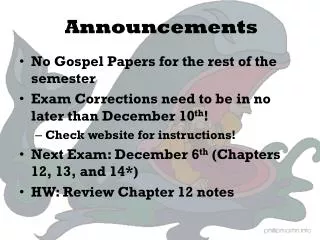
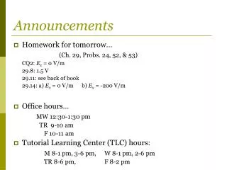
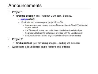
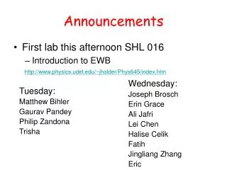
Announcements • First lab this afternoon SHL 016 • Introduction to EWB http://www.physics.udel.edu/~jholder/Phys645/index.htm Wednesday: Joseph Brosch Erin Grace Ali Jafri Lei Chen Halise Celik Fatih Jingliang Zhang Eric Tuesday: Matthew Bihler Gaurav Pandey Philip Zandona Trisha
Lecture 2 Overview • Kirchoff’s Laws • Power and Resistance • Practical sources • Voltage/ Current Dividers • DC circuit analysis • Element combination • Using Kirchoff’s Voltage Law • Using Kirchoff’s Current Law • Mesh Analysis
Kirchhoff's three laws of spectroscopy 1. A hot solid object produces light with a continuous spectrum. 2. A hot tenuous gas produces light with spectral lines at discrete wavelengths (i.e. specific colors) which depend on the energy levels of the atoms in the gas. (emission spectrum) 3. A hot solid object surrounded by a cool tenuous gas (i.e. cooler than the hot object) produces light with an almost continuous spectrum which has gaps at discrete wavelengths depending on the energy levels of the atoms in the gas. (absorption spectrum) Gustav Robert Kirchhoff (12 March 1824 – 17 October 1887)
Kirchoff’s Current Law The sum of the current at any node must equal zero: i.e., the current flowing into a node must equal the current flowing out of the node Conservation of Charge (Current = rate of change of charge) At Node 1: -i+i1+i2+i3=0 i=i1+i2+i3 Note convention: current flows from positive terminal In order for current to flow, there must exist a closed circuit
Kirchoff’s Voltage Law The sum of the voltages around a closed loop is zero Potential: at a=va b=vb Potential difference: v2=va-vb Around the loop: -v1+v2=0 v1=v2 Note: potential measured relative to ground: true ground (earth) or chassis ground (enclosure)
Circuit elements and their i-v characteristics: Resistor Ohm’s law: Current is proportional to applied Voltage, and inversely proportional to the Resistance: V=IR v R = resistance: depends on materials and geometry ρ = resistivity: depends only on materials σ = conductivity
Resistor Color code http://www.dannyg.com/examples/res2/resistor.htm 560KΩ ± 5%
Electric Power Electric power = amount of work done/unit time Voltage V = work/unit charge So, to move charge Q, work done=VQ Power = VQ/t =VI P=IV =I2R =V2/R Units = Joules/sec = Watts (W) What do we pay for in the electricity bill? kWh=energy/time × time = energy
More on Power and Resistance • What do the power ratings of appliances mean? • e.g. what does a 1000W hair dryer tell us? • Assume 120V (USA) if voltage not specified. Max current Never exceed the rated power Can you use this appliance on a 240V (UK) line? Destroys the appliance!
Resistance Limits: Open and Short Circuits • Short Circuit: A wire! R=0, V=0 for any i. • Particularly bad for any voltage source • Open circuit: A break! R→, i=0 for any V. • Particularly bad for current source
R3 Series Resistors and the Voltage Divider Rule For N resistors in series: REQ>(R1,R2,…..,RN) Voltage Divider:
Practical Voltage Sources Modelled with an ideal source and a series resistor Ideal voltage source: rS=0 Current is the same at all points voltage divider So for a practical voltage source, the output voltage depends upon RL If rS<< RL , vL = vS , independent of RL
Parallel Resistors and the Current Divider Rule For N resistors in parallel: REQ<(R1,R2,…..,RN) Current Divider: Large current through smaller R. Advantage of a parallel circuit; a broken branch will not affect other branches
Practical Current Sources Modelled with an ideal source and a parallel resistor Ideal current source: rS= current divider The output current now depends upon RL If rS>> RL , iL = iS , independent of RL
Circuit analysis method 1:Apply element combination rules Series resistors Parallel resistors Series voltage sources Parallel current sources
Circuit analysis method 1: element combination R=22Ω I= 10V/22Ω = 0.45A R1=10Ω R2=20Ω R3=30Ω V=10V Find the equivalent resistance and the current at I
Circuit analysis method 2a: KVL and KCLKirchoff’s Voltage Law The sum of the voltages around a closed loop must be zero • Draw the current direction (arbitrary) and label the voltage directions (determined by the defined current direction). Voltage on a voltage source is always from positive to negative end. • Define either clockwise or counter-clockwise as positive direction for summing voltages. Once the direction is defined, use the same convention in every loop.Voltage across a resistor is +’ve if voltage direction the same as current direction, -’ve otherwise • Apply KVL
R3 Kirchoff’s Voltage Law: Multiloop The sum of the voltages around a closed loop must be zero • Draw the current direction (arbitrary) and label the voltage directions (determined by the defined current direction). • Define either clockwise or counter-clockwise as positive voltage direction. Once the direction is defined, use the same convention in every loop. • Apply KVL
R3 Kirchoff’s Current Law The sum of the current at a node must be zero: Iin=Iout I=I2+I3 (1) ε=Ir+IR1+I2R2 (2) I3R3-I2R2 =0 (3) Set r=1Ω, R1=3Ω, R2=5Ω, R3=10Ω, ε=3V I- I2- I3 = 0 (4) 4I+5I2+ 0I3= 3 (5) 0I- 5I2+10I3= 0 (6)
Last note on KCL KVL analysis • If solutions to currents or voltages are negative, this means the real direction is opposite to what you originally defined • To deal with current sources: current is known, but assign a voltage across it which has to be solved