Atomic Absorption Spectroscopy
Atomic Absorption Spectroscopy. Content. 3.1. Theoretical Concepts 3.2. Atomic Absorption Instrumentation 3.3. Graphite Furnace Atomic Absorption 3.4. Control of Analytical Interferences. 3.1. Theoretical Concepts. The Atomic Absorption Process Theoretical Concepts

Atomic Absorption Spectroscopy
E N D
Presentation Transcript
Content 3.1. Theoretical Concepts 3.2. Atomic Absorption Instrumentation 3.3. Graphite Furnace Atomic Absorption 3.4. Control of Analytical Interferences | | 2
3.1. Theoretical Concepts • The Atomic Absorption Process • Theoretical Concepts • Quantitative Analysis • Characteristic Concentration • Detection Limits | | 3
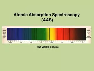
Fig3-2 Grotrian diagrams for K Fig 3-3Grotrian diagrams for Na | | 5
2. Theoretical Concepts⑴Integral Formula of AASFig 3-4 Typical Shape of A Atomic Absorption line | | 7
Integral Absorption FormulaBy atomic theory (3.1) By Line Shape Function ( the Nature distribute ) (3.2) The Peak Absorption Coefficient k0 is: (3.3) | | 8
⑵ Peak Absorption Theoryby Lambert-Beer’s Law: (3.4) (3.5) (3.6) | | 9
The Absorbance is: (3.7) | | 10
When: va>> ve, and v0a= v0e, then kv≈k0, | | 11
(3.8) | | 12
(3.9) (3.10) | | 13
3. Quantitative Analysis (3.10) | | 14
4. Characteristic Concentration (3.11) | | 15
5. Detection Limit (3.12) | | 16
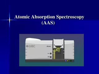
1. Photometers for AAS | | 19
1. Photometers for AAS | | 20
2. line source (Hollow Cathode Lamp ) Fig 3-13 | | 22
Hollow Cathode Lamp Emission Process Fig 3-14 | | 23
Fig 4-19 Tree Type Burner Head for different Type Flame | | 26
4. Control of Analytical Interferences Ionization interference Matrix interference Chemical interference Background interference | | 28
Ionization Interference Ba → Ba+ + e- K → K+ + e- | | 29
Matrix Interference | | 30
Chemical Interference | | 31
Background Interference | | 34
(4.13) AHCL= Aa+ Ab (4.14) AD2=Ab, (4.15) Aa = AHCL- AD2 | | 36
3.3. Graphite Furnace Atomic Absorption • Graphite furnace atomizer components • The Graphite Furnace Power Supply and Programmer • Quantitative analysis GFAAS • Effect of Matrix on Height and Area | | 37
1. Graphite furnace atomizer components The Graphite Furnace Atomizer A basic graphite furnace atomizer is comprised of the following components: · graphite tube · electrical contacts · enclosed water cooled housing · inert purge gas controls | | 38
THGA graphite tube Fig 4-27 | | 39
The Graphite Furnace Power Supply and Programmer • A Graphite Furnace Temperature Program • Drying • Pyrolysis • Cool Down(optional) • Atomization • Clean Out • Cool Down | | 40