Telecommunications System Components
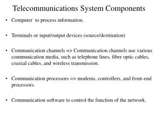
Telecommunications System Components. Computer to process information. Terminals or input/output devices (source/destination)

Telecommunications System Components
E N D
Presentation Transcript
Telecommunications System Components • Computer to process information. • Terminals or input/output devices (source/destination) • Communication channels => Communication channels use various communication media, such as telephone lines, fiber optic cables, coaxial cables, and wireless transmission. • Communication processors => modems, controllers, and front-end processors. • Communication software to control the function of the network.
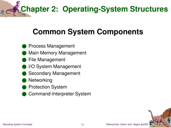
Transmission medium: Two-wire open lines Terminating connectors Single pair Flat ribbon
Transmission medium: Two-wire open lines • Simplest transmission medium.Each wire is insulated from the other and both are open to free space. • Up to 50 meters of direct connection with 19.2 kbps can be achieved. • Two types: single pair and multiple cable/flat ribbon cable. • Problems: • Crosstalk- cross-coupling of electrical signals between adjacent wires in the same cable. • Noise- The open structure makes it susceptible to the pick up of spurious noise signals from other electrical signal sources.
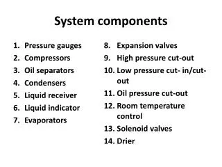
Communication Media: Twisted Wire We can reduce the effect of cross talk & noise by using twisted wire. Single pair Insulating outer cover Multicore
Communication Media: Twisted Wire • A transmission medium consisting of pairs of twisted copper wires. • We can transmit 1 Mbps over short distances (less than 100m). • They are mainly used to transmit analog signals, but they can be used for digital signals. • Advantages: inexpensive and already is in use. • Disadvantages: slow, high-speed transmission causes interference (crosstalk). • Limiting factors: skin effect & radiation effect.
Coaxial Cable In its simplest form, coaxial consists of a core made of solid copper surrounded by insulation, a braided metal shielding, and an outer cover.
Coaxial Cable It minimizes both effect: skin effect radiation effect
Coaxial Cable • A transmission medium consisting of thickly insulated copper wire, which can transmit a large volume of data than twisted wire. • Advantages: It is often used in place of twisted wire for important links in a network because it is a faster, more interference-free transmission medium (speed: 200 megabits per second). • Disadvantages: Coaxial cable is thick, is hard to wire in many buildings. It does not support analog conversations.
Optical Fiber Optical core Optical cladding Plastic coating Single core Multicore
Optical Fiber • Optical fiber consists of a glass core, surrounded by a glass cladding with slightly lower refractive index. • In most networks fiber-optic cable is used as the high-speed backbone, and twisted wire and coaxial cable are used to connect the backbone to individual devices. • Advantages: faster, lighter, and suitable for transferring large amount of data. • Disadvantages: Fiber-optic cable is more difficult to work with, more expensive, and harder to install.
The low loss regions of an optical fiber Loss db/km ÿ 50THz ² usable bandwidth 2.0 200nm 200nm 1.0 1800 1600 800 1200 1400 1000 Wavelength (nm) The low-loss regions of an optical fiber
Optical fiber • Optical fiber cable differs from both these transmission media in • that it carries the transmitted information in the form of a • fluctuating beam of light in a glass fiber. • Light transmission has much wider bandwidth, thus enabling the • transmission rate of hundreds of megabits per second. • Optical transmission is immune to electromagnetic interference • and crosstalk. • Optical fibers have less loss of signal strength than copper, • after every 30 miles we need to use a repeater, whereas in copper, • we should insert repeaters at an interval of 2.8 miles . • Optical fiber is more secure, no easy tapping on the cable, • like in copper. • Optical fibers are smaller in diameters compared to copper.
Multimode Stepped Fiber • Three types of fiber exist: multimode stepped, multimode graded, and • Single mode fibers. • In multimode stepped index fiber, the cladding and the core • material each has a different but uniform refractive index. • All the light emitted by the diode at an angle less than the critical • angle is reflected at the cladding interface and propagates along • the core by means of multiple (internal) reflections. • The received signal has a wider pulse width than the input signal. • Therefore, the maximum permissible bit rate is decreased.
Multimode Graded-Index Fiber • Dispersion can be reduced by using a core material that has a • variable (rather than constant) refractive index. • In a multimode graded index fiber, light is refracted by an • increasing amount as it moves away from the core. • Therefore, the pulse width of the received signal will be • reduced compared with stepped index fiber. • Therefore, the maximum bit rate will be higher compared to • stepped index fiber.
Single mode Fiber Single-mode Fiber: Further improvements can be obtained by reducing the core diameter to that of a single wavelength (3-10 Mm). The emitted light propagates along a single (dispersionless) path. Small core allows propagation in only one mode The bit rate will be very high.
Wireless Transmission • Wireless transmission that sends signals through air or space without any physical wire. • Common uses of wireless data transmission include pagers, cellular telephones, microwave transmissions, communication satellites, mobile data networks, personal digital assistants, television remote controls.
Satellites • Information can also be transmitted using electromagnetic (radio) • waves through free space as in satellite systems. • Satellites used for communications are generally geostationary. • Geostationary satellite orbits the earth once every 24 hours in • synchronism with the earth’s rotation . • Therefore the satellites appear stationary from the ground. • Geosynchronous satellite rotate around the earth a 6900 miles/hour • and remained positioned over the same point at 22300 miles above • the equator. • Worldwide coverage can be achieved with three geosynchronous • satellite spaced at 120 degrees interval from one another
Terrestrial Microwave • Terrestrial microwave links are widely used to provide • communication links when it is impractical or too expensive to • install physical transmission media ( e.g. across a river). • As the collimated microwave beam travels through the earth’s • atmosphere, it can be affected by weather conditions. • However, with a satellite link the beam travels mainly through • free space, therefore less prone to such effects (weather • conditions).
Radio Waves • Radio waves links are widely used to provide communication links • when it is too expensive to install fixed-wire cables. • Radio waves are used to connect a large number of data gathering • computers distributed throughout a rural area to a remote data • logging/monitoring computer.
Signal Attenuation • Any signal carried on a transmission medium is affected by • attenuation, limited bandwidth, delay distortion, and noise. • When a signal propagates along a transmission medium its • amplitude decreases. This is known as signal attenuation. • If the cable is longer, a number of repeaters (amplifiers) are • inserted at some intervals so that the receiver can detect it. • We measure both attenuation and amplification in decibels (db). • Attenuation = 10 log 10 (P1/P2) db • Amplification = 10 log 10 (P1/P2) db • Where P1 => transmitted signal power level • P2 => received signal power level
Relationship between bandwidth and the transmission capacity of a channel. • Bandwidth => The bandwidth of a channel is the range of frequencies (difference between the highest and the lowest frequencies) that can be transmitted by that channel. • The grater the range of frequencies, the greater the channel’s transmission capacity. • Baud => A change in signal from positive to negative or vice versa that is used as a measure of transmission speed.
Limited Bandwidth • Since a communications channel has a limited bandwidth, when a • signal is transmitted over a channel, only those frequency • components that are within the channel bandwidth will be received. • The larger the channel bandwidth, the more higher-frequency • components are received and hence the closer is the received signal • to the original (transmitted) signal. A formula derived by Nyquist can be used to find the capacity of the channel (cable) as a function of the bandwidth is: C = 2B log2 M where C = maximum capacity in bits per second B = bandwidth of the cable M = signaling level ( 8 - bit byte)
Bandwidth Data is to be transmitted over the PSTN using a transmission scheme with eight levels per signaling element ( 8-bit byte). If the bandwidth of the cable is 2600 Hz, deduce the Nyquist maximum data transfer rate. C = 2 x 2600 x log2 8 = 2 x 2600 x 3 = 15 600 pbs This formula is for noiseless cable, in practice, there are noises on the cable and we should use Shannon's formula. C = B log2(1+S/N)
Delay Distortion • A Digital signal consists of components with various frequencies. • The rate of propagation of a sinusoidal signal along a transmission • line varies with the frequency of the signal. • Therefore, when we transmit any signal through a transmission • line, all its components reach at the destination with varying delays. • This results in delay distortion.
Noise In the absence of a signal, a transmission line ideally has zero electrical signal present. In practice, however, there are random perturbations on the line even when no signal is being transmitted. This is called line noise level. The ration of the average power in a received signal S, to the power in noise level, N is called signal-to-noise ratio (SNR). SNR = 10 log 10 ( S / N) dB High SNR ratio indicates good-quality signal Low SNR ratio indicates low-quality signal.
Problem In practice, there are noises on the cable and we should use Shannon's formula to calculate the theoretical maximum information rate (C) of a transmission channel. C = B log2(1+S/N) where C = maximum capacity in bps B = bandwidth of the channel in Hz S/N = ratio of signal power (S) to Noise power (N) expressed in decibels or dB. Let us suppose that a phone line has a signal-to-noise power ratio of 20 dB. SNR = 10 log10 (S/N) 20 = 10 log10 (S/N) 20/10 = log10 S/N 2 = log10 S/N 10 2 = S/N Therefore S/N = 100.
Problem If this line has a bandwidth of 2600Hz. Find C (maximum theoretical information rate that can be achieved). C = 2600 x log2 (1 + 100) C = 2600 x log2 (101) = 2600 x log10 101 / log10 2 = 2600 x 2 / 0.3 = 2600 x 6.643 = 17, 270 bps
Signal Propagation Delay • There is always a finite (short) time delay for a signal to • propagate from one end of the transmission line to the other. • This is called transmission propagation delay, Tp. • Data is generally transmitted in blocks (frames) of bits. • When a block of data is reached to its destination, an • acknowledgement is sent to the sender. • Round-trip delay is the time delay between the first bit of a • block being transmitted by the sender and the last bit of its • associated acknowledgement being received. • a = Tp / Tx • where Tp = Propagation delay = D/V • where D = distance and V = velocity of electrical signal • inside the medium • Tx = Transmission delay = N/R • where N = number of bits to transfer • R = bit rate of the transmission.