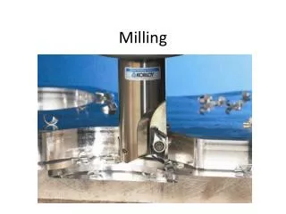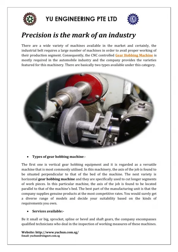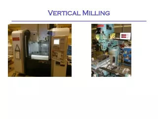
Vertical Milling
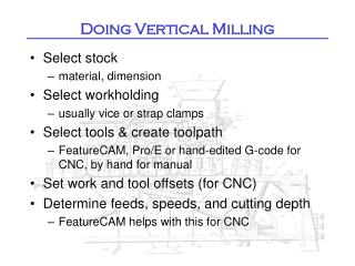
Vertical Milling. Doing Vertical Milling. Select stock material, dimension Select workholding usually vise or strap clamps Select tools & create toolpath Esprit, FeatureCAM, Creo or hand-edited G-code for CNC, by hand for manual MfgSuite does accurate simulation of G-code.


Vertical Milling
E N D
Presentation Transcript
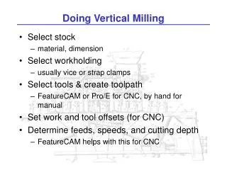
Doing Vertical Milling • Select stock • material, dimension • Select workholding • usually vise or strap clamps • Select tools & create toolpath • Esprit, FeatureCAM, Creo or hand-edited G-code for CNC, by hand for manual • MfgSuite does accurate simulation of G-code. • Set work and tool offsets (for CNC) • Determine feeds, speeds, and cutting depth • Esprit and FeatureCAM help with this for CNC
Example Program % O0010 (SIMPLE EXAMPLE FOR NVX) (OP1- TOP SIDE) (STOCK- 50MM X 40MM X 50MM) (G54 ZERO- LEFT FRONT TOP) G54 G00 G40 G90 G17 G21 (SPOT DRILL HOLES) T7 M6 G43 H7 S2000 M3 M8 G0 X12.5 Y12.5 Z2.5 G81 Z-2.5 R2.5 F250.0; (CANNED DRILL CYCLE) X12.5 Y25.0 X25.0 Y25.0 X25.0 Y12.5 G80 G0 Z2.5; (CANCEL CANNED CYCLE) M9 M5 (DRILL 6.35MM HOLES) G28 Z0 T9 M6 G43 H9 S2000 M3 M8 G0 X12.5 Y12.5 Z2.5 G83 Z-2.5 Q2.5 R2.5 F250.0; (CANNED DRILL CYCLE) X12.5 Y25.0 X25.0 Y25.0 X25.0 Y12.5 G80 G0 Z2.5; (CANCEL CANNED CYCLE) M9 M5 G28 Z0 M30 %
Work Offsets • Work Offsets • G54-G59 • G54 X & Y aligned with vice jaw left front • Set G54 Z = -660.0 + height to desired Z0
Tool Offsets • Enter tool data in offset table • Put tool in spindle • Indicate tool number in TOOL REGISTRATION screen
Tool Offsets • Run program O0002, move tool close to sensor, press START again.
Process • Rigidity: • use shortest tool and tool holder • deflection of tool or work causes form error • keep workpiece firmly clamped and supported • avoid speed/feed/depth combos that chatter • Heat: • use carbide tools when heat is a problem • keep chips cleared (liquid or air coolant) • hard chips get harder • soft chips stick to tool • don’t go too fast OR too slow • Chip load: • keep volume removed constant! • especially watch tool entry, exit, corners
Setting Feeds & Speeds • http://www.custompartnet.com/calculator/milling-speed-and-feed
Vibration • For Max Material Removal Rate: • Choose highest spindle RPM • Tune tool length to stay in a stable lobe at top spindle RPM