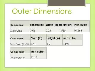
Outer Dimensions
This document details an analytical and experimental approach to assess heat conduction in chip components, specifically utilizing hand calculations to derive thermal parameters and energy dissipation. The analysis focuses on a chip section measuring 0.1” x 0.1” with a total heat transfer of 1.6W, examining the impact of air as an insulator. Experimental results indicate that, after running an RFID reader for 20 minutes, the chip temperature peaked at 128°F while the ambient temperature reached 116°F, illustrating the effectiveness of air in thermal management.

Outer Dimensions
E N D
Presentation Transcript
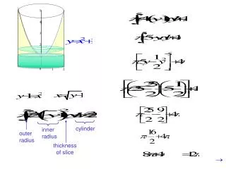
Heat Analysis – Hand Calculations • Conduction caused by air: • Section of chip 0.1” x 0.1” • A=6.45*10-6 m2 • Q= -KA (dT/dx) • QTotal=1.6W • QPart =1.6W/210 = 0.00762W • K= (about) 0.0257 Wm-1K-1 • dT/dx = Q/(-KA) • dT/dx = 0.00762/(0.0257*6.45*10-6) = 45969 degC/m =649 degF/in =64.9 degF/0.1in Not conclusive, but a good representation that air acts as an insulator Air Chip
Heat – Experimental Results RFID Reader connected to power in case until it reaches steady state Antenna run on full power for 20 minutes Chip temperature reached about 128 deg F Ambient inside case temp reached about 116 deg F
Heat – Analytical Analysis Case thermal conductivity = 0.2 Wm-1K-1 Outside case temp set to 20 deg F Top of chip set to 130 deg F Bottom of chip insulated