Download
1 / 28
280 likes | 640 Vues
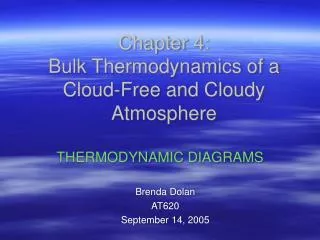
Chapter 4: Bulk Thermodynamics of a Cloud-Free and Cloudy Atmosphere. THERMODYNAMIC DIAGRAMS. Brenda Dolan AT620 September 14, 2005. Recall…. In the first part of the chapter, we derived various forms of the 1st Law of Thermodynamics under moist conditions, and for a cloud-free atmosphere

E N D
Chapter 4:Bulk Thermodynamics of a Cloud-Free and Cloudy Atmosphere THERMODYNAMIC DIAGRAMS Brenda Dolan AT620 September 14, 2005
Recall… • In the first part of the chapter, we derived various forms of the 1st Law of Thermodynamics under moist conditions, and for a cloud-free atmosphere • Most generally, 1st law for open thermodynamic multi-phase system: Vapor ice Heat storage radiation dissipation • For a cloud-free atmosphere:
Recall… • We also introduced thermodynamic variables which are conserved for adiabatic motions: • θ: Potential temperature • Conserved for dry, isentropic motions • θl,i: Ice-liquid water potential temperature • Conserved for wet adiabatic (liquid and ice transformations) • Reduces to θ in the absence of cloud or precip. • θe: Equivalent potential temperature • Useful in diagnostic studies as a tracer of air parcel motions • Conserved during moist and dry adiabatic processes • θeiv is conservative over phase changes but not if precipitation fluxes exist
Recall… • Wet-Bulb temperature, Tw • Temperature that results from evaporating water at constant pressure from a wet bulb • Wet-bulb potential temperature, θw • Determined graphically • Conserved during moist and dry adiabatic processes (as is θe)
Recall… • Energy Variables • Dry static energy (s) • Moist static energy (h) • In water-saturated environ: • Static energy (S) • Mosit Static energy (H)
4.6 Thermodynamic Diagrams • Provide graphical display of lines representing major kinds of processes to which air may be subject • Isobaric, isothermal, dry adiabatic and pseudoadiabatic processes
4.6 Thermodynamic Diagrams • Three desirable characteristics • Area enclosed by lines representing any cyclic process be proportional to the change in energy or the work done during the process(in fact, designation thermodynamic diagram is reserved for only those in which area is proportional to work or energy) • As many as possible of the fundamental lines be straight • The angle between the isotherms and the dry adiabats shall be as large as possible (90º) - makes it easier to detect variations in slope
Thermodynamic diagrams • Would like to use p-α, but the angle between isotherms and adiabats is too small • To preserve the area enclosed on one diagram to be equal to the area enclosed on another, we found: • Thus, if we specify the thermodynamic variable B, we can determine what A must be in order to have an equal-area transformation from α, -p to A,B
Tephigram • Let B=T • Now determine A: From eqn. 4.37: • Plug in B=T: • From ideal gas: pα=RT => p=RT/α
Tephigram • Not real useful to plot… introduce Poisson’s equation to get potential temperature:
Tephigram • Take the log and solve for lnα: • Now back to A: • Arbitrarily choose F(T)=-G(T), resulting in the following coordinates: (4.38)
Tephigram • We also know cplnθ as entropy (ϕ), leading the developer of this diagram, Sir Napier Shaw, to call it the T- ϕ diagram, or tephigram • The equation for the isobars can be found by taking the logarithm of Poisson’s equation:
Properties of a Tephigram • Isobars are logarithmic curves sloping upward to the right, decreasing in slope with increasing temperature (because of log vs. linear coordinates) • Pseudoadiabats are curved • Recall, a pseudoadiabat is a moist-adiabatic process in which the liquid water that condenses is assumed to be removed as soon as it is formed, by idealized instantaneous precipitation. • Saturation mixing ratio lines are nearly straight • Angle between isotherms and adiabats is exactly 90º • Thus, changes in slope are easily detected and compared
Tephigram-Summary • Tephigram is Coordinates are: • Area proportional to energy • Four sets of lines which are exactly or nearly straight and only one set which is curved • An isotherm-to-adiabat angle of 90º Satisfies all three criteria nearly perfectly! • Especially useful in tropics
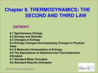
Tephigram--Example Dry adiabatic lapse rate isotherms isobars moist adiabatic lapse rate Saturation mixing ratio
Skew T-log p Diagram • Introduced by Herlofson in 1947, to make the isotherm-adiabat angle more 90º • B=-lnp • Thus, equation 4.37 becomes • Which reduces to: (4.39)
Skew T-log p Diagram • Integrating and holding lnp (and therefore p) constant: (4.40) • Choosing an arbitrary function, F(lnp)=-Klnp, where K is a constant we choose, and realizing that we are not concerned with the sign of the area (it only determines the direction of the cycle), we arrive at the coordinates for a Skew T-log p: (4.41) • B is the ordinate and A is the abscissa
Skew T-log p Diagram • Isotherms have the equation: or or (4.42) • The equation for the dry adiabats is found by taking the log of Poisson’s equation while holding θ constant:
Properties of a Skew T-log p • Isotherms are straight parallel lines whose slope depends on the value of K • If K is chosen to make the isotherm-adiabat angle close to 90º, then the isotherms slope upward to the right at an angle of ~45º to the isobars • Adiabats are gently, but visibly, curved, since Rlnp is one of the coordinates but lnT is not. They run from lower right to the upper left of the diagram, concave upwards • Pseudoadiabats are distinctly curved • This is true of all diagrams which preserve the energy-area proportionality • Saturation mixing ratio lines are essentially straight
Skew T-log p--Summary • Skew-T is Coordinates are: • Area proportional to energy • Three sets of exactly or closely straight lines; one set of gently curved lines, and only one set which is markedly curved • An isotherm-to-adiabat angle which varies with position on the diagram but is about 90º Satisfies all three criteria!
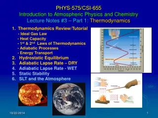
Skew T-log p--Example Dry adiabats (θ) isobars isotherms moist adiabatic lapse rate Saturation mixing ratio
Stüve Diagram • B=T • A=pk • Pk is on the ordinate with p increasing downward, and T on a linear scale • PROPERTIES • Dry Adiabats are straight lines • Pseudoadiabats are curved • Saturation mixing ratio lines are essentially straight • Adiabat-isotherm angle is usually ~45º • NOT an equal-area transformation of α,-p, so the area is not proportional to energy • Not as widely used anymore • (Also called pseudo-adiabatic)
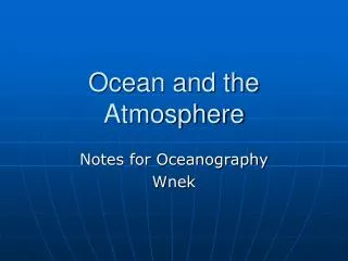
Stüve Diagram isobars moist adiabatic lapse rate Dry adiabatic lapse rate Saturation mixing ratio isotherms
Thermodynamic Diagram Choice • There are many thermodynamic diagrams (Aerogram, Clapeyron, Emagram, pastagram, Thetagram…) • Most meteorologists seem to have an aversion to diagrams other than the one with which they are most familiar • Not a great deal of difference between various diagrams • Sometimes one diagram is preferred over another because of excellence of the printing, the skillful use of color, and minimization of eye strain. • In other cases, the deciding factor may be the presence or absence of some auxiliary graphical calculating device (ie: for rapidly calculating the distance between pressure levels) • Over-all, it seems that the tephigram and the skew T-log p are superior to all others by a small margin, but it is likely many of the major diagrams will continue for many years.