Internal Architecture of 8086
320 likes | 985 Vues
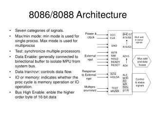
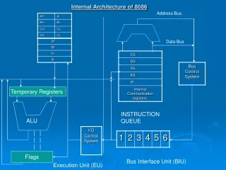
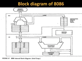
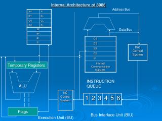
Address Bus. Data Bus. Internal Architecture of 8086. Temporary Registers. INSTRUCTION QUEUE. ALU. | | | | | |. Flags. Bus Interface Unit (BIU). Execution Unit (EU). The 8086 microprocessor is internally divided into two separate functional unit:.

Internal Architecture of 8086
E N D
Presentation Transcript
Address Bus Data Bus Internal Architecture of 8086 Temporary Registers INSTRUCTION QUEUE ALU | | | | | | Flags Bus Interface Unit (BIU) Execution Unit (EU)
The 8086 microprocessor is internally divided into two separate functional unit: • Bus Interface Unit: This unit fetches instructions, reads data from memory and ports, and writes data to memory and i/o ports. The BIU interfaces the 8086 to the outside world. It contains: • Instruction Queue: The BIU Instruction Queue is a FIFO group of registers in which up to 6 bytes of instruction code are perfected form memory ahead of time. This is done in order to speed up program execution by overlapping instruction fetch with execution. • Adder: The BIU contains a dedicated adder which is used to produce the 20 bit address • Bus Control Circuitry: The Bus Control Circuitry logic of a BIU generates all the bus control signals such as READ, WRITE for memory or I/O • Segment Registers: The BIU has four 16 bit segment registers. These are: Code segment: All program instructions must be located in main memory pointed to by the 16 bit CS register with a 16 bit offset in the segment contained in the 16 bit instruction pointer (IP) • Stack segment: The SS register points to the current stack. The 20 bit physical address is calculated from the SS and SP for stack instructions such as PUSH and POP. • Data segment: The DS register points to the current data segment, operands for most instructions are fetched from this segment. The 16 bit contents of the SI or DI or a 16 bit displacement are used as offset for computing the 20 bit physical address. • Extra segment: The ES register points to the extra segment in which data (in excess of 64K pointed to by the DS. String instruction always use the ES and DI to determine the 20 bit physical address for the destination • b. Execution Unit (EU): The EU decodes and executes instructions. A decoder in the EU control system translates instructions. The EU has a 16 bit ALU for performing arithmetic and logic operations. The EU has eight 16-bit general registers. These are AX,BX,CX,DX,SP,BP,SI and DI. • The flag registers in the EU holds the status flags after an ALU operation.
The DX register is used to hold the high 16 bit result in 16X16 multiplication or the high 16 bit dividend before a 32%16 division and the 16 bit remainder after the division The two pointer registers SP and BP are used to access data in the stack segment. The two index registers SI and DI are used in indexed addressing mode. Note that instructions that process data strings use the SI and DI index registers together with the DS and ES respectively in order to distinguish between the source and destination addresses. The 8086 has six one-bit flags: CF,OF,ZF,AF,PE,SF. The 8086 has three control flags: DF,TF,IF EA: The execution unit calculates an offset from the instruction for a memory operand. This offset is called the operands effective address. It is a 16 bit number that represents the operands distance in bytes form the start of the segment in which it resides
8086 Addressing Modes: The basic and other addressing modes can be classified into five groups: 1. Addressing mode for Accessing Immediate and Register Data: a. Register Addressing Mode: In this mode, source and destination or both may be contained in registers Example: MOVE DX,CX b. Immediate Addressing Mode: In this mode 8 or 16 bit data can be specified as part of the instruction. Example: MOVE DX,0502H 2. Addressing Modes for Accessing Data in Memory (Memory Modes): The EU has direct asscess to all registers and data for register and immediate modes. However the EU cannot directly access the memory operands. It must be used BIU in order to access memory operand. a. Direct Addressing Mode: In this mode the effective address is taken directly from the displacement field of the instruction. Ex: MOV BX, START, moves the contents of the 20 bit address computed form the segment register DS and START into BX. Example: MOVE CX,DS:START b. Register Indirect Mode: The EA of a memory operand may be taken directly from one of the base or index registers (BX,BP,SI,DI). Ex: consider MOV CX,[BX]. If DS=2000,BX=0004 and 20004=0224, then after execution MOV CX,[BX] the contents of CX is 0224. Example: MOVE [DI],BX
c. Based Addressing Mode: In this mode the effective address is the sum of a displacement value and the contents of register BX or BP Example: MOVE AX,START[BX], moves the contents of the 20 bit address computed form the segment register and [BX]+START into AX. The segment register is DS or SS. d. Indexed Addressing Mode: In this mode the effective address is calculated from the sum of a displacement value and the contents of register SI or DI Example: MOVE AX,START[SI] e. Based Indexed Addressing Mode: In this mode the effective address is calculated from the sum of a base register (BX or BP), an index register (SI or DI) and a displacement. Example: MOVE AX,4[BX] [SI] moves the contents of the 20 bit address computed form the segment register and [BX]+[SI]+4 into AX. The segment register is DS. f. String Addressing Mode: This mode uses index registers. SI is assumed to point to the first byte or word of the source string and DI is assumed to point to the first byte or word of the destination when a string instruction is executed. The DI and SI is automatically decrement and increment to point to the next byte of word depending of DF. The default segment register for source is DS and for destination is ES. Example: MOVES BYTE where [DF]=0,[DS]=2000H,[ES]=4000H,[SI]=0500H,[DI]=0300H,[20500]=38H, [40300]=45H. After executes the above instructions [40300]=38H,[SI]=0501H,[DI]=0301H 3. Addressing Modes for Accessing I/O Ports (I/O Modes) a. Direct Port Addressing Mode: Example: OUT 05H,AL b. Indirect Port Addressing Mode: Example: OUT AL,DX
4. Relative Addressing Mode Example: JNC START 5. Implied Addressing Mode Example: CLC. • 8086 Instruction Set: • The 8086 has approximately 117 different instructions set. The 8086 instruction contains no operand, single operand, and two operand instructions.8086 do not permit memory-to-memory operations. Different types of instruction of 8086 are given below: • Data transfer instructions: Data transfer instructions generally involve two operands, the source and destination. The source can be a register or a memory or immediate data. The destination can be a register or a memory location. This instruction do not affect CPU flags. The various data transfer instructions such as: • MOVE: This instruction transfer a byte or a word from source to the destination. • Example: MOVE CX,DX
PUSH START[BX] pushes the 16-bit contents of two memory locations starting at the 20-bit physical address computed from START,BX, and DX after decrementing SP by 2. 2. Input/Output Instructions: Example: IN AL,DX inputs 8-bit data from 8-bit port contained [DX] into AL. 3.Arithmetic Instructions: Example: DAA is used to adjust the result of adding two packed BCD numbers in AL to provide a valid BCD number. Consider adding two packed BCD digits 55 with 18 as follows: ADD SL,DL ; [AL]=55 BCD [DL]=18 BCD RESULT [AL]=6DH DAA Since low nibble is greater than 9 so add 1101+0110 1 0110 Carry 3BCD Final Result =73 BCD 4. Shift and Rotate Instruction: In the shift or rotate operation, the destination operand specifies the register or memory to be shifted or rotated while the source operand specifies the number of times the register or memory contents are to be shifted. Example: SHL DX,1 Logically shifts the 16-bit contents of DX once to left.
5. Branch Instructions: A branch instructions transfer control from the normal sequence of instructions execution to the specified destination or target instruction. Example: JMP START, this instruction unconditionally transfer control to the target location. CALL BX, the instruction transfer control to a subprogram 6.Processor Control Instruction: The 8086 processors supports a variety of instructions modifying the CPU status flag register called as the processor control instructions. Such as CLC,CLS,HLT. 7. String Instructions: The 8086 supports string instructions for string movement, load and store. Example: MOVESB this instruction moves bytes from source string to the destination string. 8086 Memory Bank: The address space is physically implemented in a 16-bit data bus by dividing the address space into two banks of up to 512K bytes as in bellow fig:
8086 Memory This bank can be selected by BHE and A0 as follows:
One bank is connected to D7-D0 and contains all even addressed bytes (A0=0). The other bank is connected to D15-D8 and contains odd-addressed bytes (A0=1). A particular bytes in each bank is addressed by A19-A0. As an example, consider execution of the instruction MOVE DH,[BX] Suppose the 20-bit address calculated by BX and DS is even. The 8086 output LOW on A0 and HIGH on BHE. This will select the even address bank. The output of the selected memory is placed on the D7-D0 lines by the memory chip. The 8086 reads this data via D7-D0 and automatically placed it in DL.
![8086 [2]](https://cdn1.slideserve.com/2457127/8086-2-dt.jpg)