Download

1 / 38
390 likes | 542 Vues
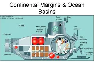
ANFOG: Australian National Facility for Ocean Gliders. Basics of an Ocean Glider. Related to ARGO floats – but with wings Powered by batteries (C or D cells) Buoyancy engine – pumping oil or water into and out of a bladder changes density of vehicle which causes glider to sink or float

E N D
ANFOG: Australian National Facility for Ocean Gliders
Basics of an Ocean Glider • Related to ARGO floats – but with wings • Powered by batteries (C or D cells) • Buoyancy engine – pumping oil or water into and out of a bladder changes density of vehicle which causes glider to sink or float • Wings provide forward momentum – motion through the water is a saw tooth pattern • Control via a rudder or movement of battery pack fore to aft and side to side
Ocean Gliders Description • Operation depth ratings 200, 1000, 5000 m • Designed for launch, monitor, recover or launch, forget, recover missions • Mission duration 15 days – 6 months • Speed < 1 kn - typically 0.2-0.5 knts • Weight – 50-75 kgs in air • Monitored and programmed at surface from control stations located on your desktop. • R/T communications at surface viaradio link, Iridium, cell, Argos • Easily deployed and recovered from small boats or docks by 1 or 2 persons • Operations in all weather
Glider Manufacturers 3 groups in US building vehicles • Webb Research – Slocum Glider, Thermal Glider • UofW/APL – Seaglider • Scripps Institute - Spray Glider (now Bluefin)
Slocum Electric Glider Manufactured by Webb Research, USA
Development Timeline • 1989 “The Slocum Mission” appears in Oceanography • 1990 Office of Naval Technology (ONT) awards Webb Research Corporation contract for development of Slocum prototype • 1991 Tests of Slocum prototype and thermal engine in Wakulla Springs FL and Lake Seneca NY • 1992 First deployment of the ALBAC glider, a shuttle type glider developed at the University of Tokyo in the lab of Tamaki Ura. The ALBAC design uses a drop weight to drive the glider in a single dive cycle between deployment and recovery from ship. It uses a moving internal mass to control pitch and roll. • 1993 Autonomous Oceanographic Sampling Networks paper appears in Oceanography
Development Timeline • 1999 Slocum gliders tested at LEO-15 Observatory NJ • 1999 Autonomous Ocean Sampling Network (AOSN) I conducted in Monterey Bay, CA to make oceanographic surveys. A prototype Spray operates for 11 days. Three Seagliders were also deployed in the bay. • 2000 By this time all three gliders, Spray, Slocum, and Seaglider, have completed 10 day missions • 2001 Spray glider makes 280 km section from San Diego • 2002 Seaglider travels 1000+ km off Washington Coast. Another Seaglider is deployed for month in storms off shelf near Seward Alaska • 2003 January. Deployment of three Slocum gliders in the Bahamas by WHOI. Trials of prototype thermal Slocum conducted by WRC on same cruise
Development Timeline • 2003 February. SPAWAR and the Canadian Navy conduct tests in the Gullf of Mexico of 3 Slocum electric gliders. • 2003 August – September. AOSN II conducted in Monterey Bay CA. Gliders are used to make extensive oceanographic surveys over a six week period. Twelve Slocum and five Spray gliders are deployed during the experiment, to date the most gliders deployed for one project. • 2004 September – November. A Spray glider travels across the Gulf Stream, beginning about 100 miles south of Nantucket, MA and arriving near Bermuda about one month later. The glider travels 600 miles, at a speed of about 0.5 miles per hour or 12 miles per day. • 2004 Sea Gliders operate through a typhoon off east Asia • 2005 Two Sea Gliders fly from Washington coast to Hawaii – 6 month mission • 2005 Gliders launched from US Submarine
Ocean Glider Census – ~150 vehicles* * June 2006
Benefits • ‘cheaper’ to operate when cf with shipborne observations • Operations in all weather • Designed for launch, monitor, recover or launch, forget, recover missions • Telemetry rates via low earth orbit satellites are sufficiently inexpensive in both energy (~30 J/kilobyte) and cost (~$0.20/kilobyte) that the data return from a single glider (~120 kilobytes/day) is nearly that originally envisioned for the entire 3000-float Argo fleet using ARGOS while being a factor of ~200 less expensive.
Gliders are tools for appropriate Missions • Need to balance quality of data spatial requirements temporal requirements costs • to select best overall performance and value • Glider mission can be changed at any time
Temperature Conductivity Salinity Depth Wavelength backscatter Fluorescence sensor Beam attenuation Passive Acoustics Sensor Capabilities Real-time data available through the web Delayed mode calibrated, QC data available
Slocum Electric Glider Manufactured by Webb Research, USA
Slocum Electric Glider • SENSORS • CTD (conductivity, temperature, depth) - SeaBird • Dissolved oxygen – Aanderaa Optode • Fluorescence: Chlorophyll-a, CDOM (coloured dissolved organic matter), Phycoerythrin - Wetlabs • Optical Backscatter:: turbidity through backscattered light at 470nm (blue), 530 nm (Green), 660nm (red).
Investment plan Glider Purchase: 5 shallow (200m) and 5 deep (1000m) (30%) People: 3 people: glider preparation; Glider deployment and control; data provision (QC) (30%) Glider deployments: Data transmission costs, shipping (30%) Schedule: 2 shallow water gliders to be delivered in June 2007 2 deep water gliders to be delivered in November 2007 Others to come onboard in 2008.