Download
1 / 19
190 likes | 208 Vues
Learn the critical success factors in database design and the phases of conceptual and logical design, including drawing ER diagrams, refining conceptual models, applying normalization rules, and converting ERD to relational data models. Understand key concepts like entities, attributes, relationships, and keys.

E N D
Entity-Relationship Modeland Diagrams (continued) Todd S. Bacastow IST 210 Organization of data
Database Design Conceptual design Entity-Relationship Model Logical design Logical Schema Physical design
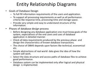
Critical Success Factors in Database Design • Work interactively with the users as much as possible • Follow a methodology throughout the data modeling process • Incorporate structural and integrity considerations into the data models • Combine conceptualization, normalization, and validation techniques into the methodology
ERD as a “Semantic Model” • Semantics: Relationships between symbols and their meanings. • A semantic model attempts to capture the meaning of user's information and provide a concise, high-level description of that information. • The information is represented by logical associations (relations) between pairs of objects and by the classification of objects into categories (entities).
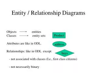
Entity, Attribute, Relationship Name Address Numb CLIENT PASSPORT Exp • A client must have a passport • Each client has only one passport • A client may have one or more itinerates • An itinerary belongs to one client ITINERARY city Date
Basic relationships One-to-One HUSBAND WIFE • A husband has one wife • A wife has one husband One-to-Many TEAM PARTICIPANT • A team has many participants • Many participants belong to one team Many-to-Many EMPLOYEE SKILL • An employee has many skills • Many employees have the same skill
Exercise • Business rules: A university where a student may take many courses employs lecturers. Each lecturer teaches one or more courses but no course is taught by more than one lecturer. Each student has to complete two or three assignments for each course. • Requirement: Draw an entity relationship (ER) diagram for the situation described.
Solution Complete Has Take Teach
Review • Use ER Diagrams to help understand • The essential information • Visual guide to the organization • Plan for how to proceed • Improve database design
Logical design phase Conceptual E-R Model 1. REFINE THE CONCEPTUAL MODEL Refined Conceptual Model 2.APPLY THE RULES OF NORMALIZATION Logical Data Model
Table1 Going from this: To this: Table2 Table5 Table3 Table4 The Next Step
Logical Database Design • Main objectives of relational databases is to ensure that each item of data is held only once within the database: • Minimize the amount of storage space • Simplify updating procedures • Ensure that data is accurate • Done by converting ERD into well-structured relational data model
Relational Data Model E-R Model helps to define the underlying tables CUSTOMER CUSTOMER receive INVOICE INVOICE
Converting ERD to tables • Convert each of the entities (E1 & E2) in to a table. The attributes of the entity become attributes of the table. • Convert each relationship (R1) with a many-to-many cardinality in to a table. The primary keys of the entities (E1 & E2) linked by the relationship and attributes of the relationship A1 become attributes of the resulting table. • Do not convert relationships (R1) with one-to-many or one-to-one cardinality in to a table. • For a one-to-one relationship, add the attributes of the relationship (A1) and the primary key of either table (T1 or T2) into the other table (T1 or T2). • For a one-to-many relationship, add the attributes of the relationship (A1) and the primary key to the other table. Relationship1 R1 Entity 1 E1 Entity 2 E2 A1
Fields and Records • Field: a single column of information in a table • Appears as an attribute in the ERD • Key: a field which uniquely identifies each record in a field Field Key
Fields and Records • Foreign Key: links tables by referencing a key in another table • Tuple: the full set of information about one occurrence of the entity • All information included in a single row of the table Foreign Key Tuple
Review • The key conversion tasks are: • Create entity tables • Resolve relationships • Resolve multi-valued and composite attributes • Insert primary and foreign keys • Normalize to Third Normal Form (we will talk about this next time) • Integrity constraints
Review • Relations • Just another name for a table • Every relation has a unique name • Every attribute value is atomic • Every row is unique • Attributes in tables have unique names • The order of the columns is irrelevant • The order of the rows is irrelevant