EEM 486 : Computer Architecture Designing a Multicycle Processor
EEM 486 : Computer Architecture Designing a Multicycle Processor. Processor. Input. Control. Memory. Datapath. Output. The Big Picture. Designing a Multiple Clock Cycle Datapath. OPcode. Control Logic / Store (PLA, ROM). Decode. microinstruction. Conditions. Instruction.

EEM 486 : Computer Architecture Designing a Multicycle Processor
E N D
Presentation Transcript
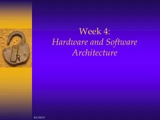
EEM 486: Computer ArchitectureDesigning a Multicycle Processor
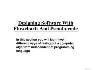
Processor Input Control Memory Datapath Output The Big Picture • Designing a MultipleClock CycleDatapath
OPcode Control Logic / Store (PLA, ROM) Decode microinstruction Conditions Instruction Control Points Datapath Single-CycleProcessor In our single-cycle processor, each instruction is realized by exactly one control command or microinstruction
Main Control op ALU control fun ALUSrc Equal ExtOp MemWr MemWr RegWr MemRd RegDst nPC_sel ALUctr Reg. Wrt ALU Register Fetch Ext Mem Access PC Instruction Fetch Next PC Data Mem Abstract View ofSingle Cycle-Processor
What’s Wrong with CPI=1 Processor? Arithmetic & Logical PC Inst Memory Reg File ALU setup mux mux • Long Cycle Time • All instructions take as much time as the slowest • Real memory is not as nice as our idealized memory • Cannot always get the job done in one (short) cycle Load PC Inst Memory Reg File ALU Data Mem setup mux mux Critical Path Store Inst Memory PC Reg File ALU Data Mem mux Branch PC Inst Memory Reg File cmp mux
Storage Array selected word line storage cell address bit line address decoder sense amps mem. bus proc. bus L2 Cache memory Processor Cache 1 time-period 20 - 50 time-periods 2-3 time-periods Memory Access Time • Physics fast memories are small (large memories are slow) • Use a hierarchy of memories
Multicycle Approach • Break up the instructions into steps: • Leteach step take one “smaller” clockcycle - Balancethe amount of work to be done - Restrict each cycle to use only one major functional unit Majorfunctionalunits: Memory, Register File, and ALU • Letdifferentinstructionstakedifferentnumbers of cycles • Use a functionalunitmorethanoncewithinexecution of oneinstruction (Less hardware) • A singlememoryunitforbothinstructionsand data • A single ALU, ratherthan an ALU andtwoadders • At the end of a cycle • store values for use in later cycles • introduce additional “internal” registers
Equal Partitioning the CPI=1 Datapath • Add registers between smallest steps MemWr MemWr RegWr MemRd RegDst nPC_sel ALUSrc ExtOp ALUctr Reg. File Exec Operand Fetch Instruction Fetch Mem Access PC Next PC Data Mem Write back Memory access Execution Instruction fetch Decode and Operand fetch
Recall: Step-by-step Processor Design Step 1: ISA Logical Register Transfers Step 2: Components of the Datapath Step 3: RTL + Components Datapath Step 4: Datapath + Logical RTs Physical RTs Step 5: Physical RTs Control
Step 4: R-type (add, sub, . . .) inst Logical Register Transfers ADDU R[rd]<–R[rs] + R[rt]; PC <– PC + 4 Step 1. InstructionFetch IR ← MEM[PC], PC ← PC + 4 Step 2. InstructionDecodeandRegisterFetch A ← R[rs], B ← R[rt] Step 3. Execution ALUOut ← A op B Step 4. Write-back R[rd] ← ALUOut
ALUSrcA RegWrite MemWrite nPCWrite MemRead IRWrite Instruction [31-26] PC Address Instruction [25-21] Memory Rs Read data 1 B A MemData Instruction [20-16] Rt ALU Out Registers Write data Instruction [15-11] Read data 2 Instruction [15-0] Rw 4 Write data Instruction register ALU 0 0 1 1 ALUctr ALUSrcB Step 4: R-type (add, sub, . . .)
Step 4: Logical immediate inst Logical Register Transfers ORI R[rt] <– R[rs] OR ZExt(Im16);PC <– PC + 4 Step 1. Instruction Fetch IR ← MEM[PC], PC ← PC + 4 Step 2. Instruction Decode and Register Fetch A ← R[rs] Step 3. Execution ALUOut ← A OR ZExt(Im16) Step 4. Write-back R[rt] ← ALUOut
RegDst ALUSrcA RegWrite MemWrite nPCWrite MemRead IRWrite Instruction [31-26] Address PC Memory Instruction [25-21] Rs 0 Read data 1 A 1 MemData ALU Instruction [20-16] Rt ALU Out Registers Write data 0 B Read data 2 0 Inst [15-11] Instruction [15-0] Rw 1 1 4 Write data Instruction register 2 Zero extend 16 32 ALUctr ALUSrcB Step 4: Logical immediate
Step 4 : Load inst Logical Register Transfers LW R[rt] <– MEM[R[rs] + SExt(Im16)];PC <– PC + 4 Step 1. Instruction Fetch IR ← MEM[PC], PC ← PC + 4 Step 2. Instruction Decode and Register Fetch A ← R[rs] Step 3. Memory address computation ALUOut ← A + SExt(Im16) Step 4. Memory access MDR ← Memory[ALUOut] Step 5. Load completion R[rt] ← MDR
RegDst ALUSrcA RegWrite MemWrite nPCWrite MemRead IRWrite Instruction [31-26] Address PC Instruction [25-21] Memory Rs 0 0 Read data 1 A 1 1 MemData ALU Instruction [20-16] Rt ALU Out Registers Write data 0 B Read data 2 0 0 Inst [15-11] Instruction [15-0] Rw 1 1 1 4 Write data Instruction register 2 Extender MDR 16 32 ALUctr ALUSrcB ExtOp MemtoReg IorD Step 4 : Load
Step 4 : Store inst Logical Register Transfers SW MEM[R[rs] + SExt(Im16)] <– R[rt];PC <– PC + 4 Step 1. Instruction Fetch IR ← MEM[PC], PC ← PC + 4 Step 2. Instruction Decode and Register Fetch A ← R[rs], B ← R[rt] Step 3. Memory address computation ALUOut ← A + SExt(Im16) Step 4. Memory access Memory[ALUOut] ← B
RegDst ALUSrcA RegWrite MemWrite nPCWrite MemRead IRWrite Instruction [31-26] Address PC Instruction [25-21] Memory Rs 0 0 Read data 1 A 1 1 MemData Instruction [20-16] Rt ALU Out Registers ALU Write data 0 B Read data 2 0 0 Inst [15-11] Instruction [15-0] Rw 1 1 1 4 Write data Instruction register 2 Extender MDR 16 32 IorD ALUctr ALUSrcB MemtoReg ExtOp Step 4 : Store
Step 4 : Branch inst Logical Register Transfers BEQ if R[rs] == R[rt]then PC <= PC + 4+SExt(Im16) || 00 else PC <= PC + 4 Step 1. InstructionFetch IR ← MEM[PC], PC ← PC + 4 Step 2. InstructionDecodeandRegisterFetch A ← R[rs], B ← R[rt] ALUOut ← PC +SExt(Im16) || 00 Step 3. Branchcompletion If A = B, PC ← ALUOut
PCWriteCond PCWrite MemWrite MemRead RegDst PCSource ALUSrcA RegWrite IRWrite Instruction [31-26] Address 1 0 0 Memory PC Instruction [25-21] Rs 1 0 1 Read data 1 MemData A Zero Write data Instruction [20-16] Rt ALU Out Registers ALU 0 0 0 B Read data 2 1 1 Inst [15-11] Instruction [15-0] Rw 1 4 Write data Instruction register 2 3 Shift left 2 MDR Extender 16 32 IorD ALUctr ExtOp ALUSrcB MemtoReg Step 4 :Branch
PCWriteCond ALUOp PCWrite PCSource IorD ALUSrcB MemRead ALUSrcA Control MemWrite RegWrite ExtOp Op [5-0] MemtoReg RegDst IRWrite Instruction [31-26] 0 1 0 Address PC Instruction [25-21] 0 1 1 Rs Memory Read data 1 A MemData Instruction [20-16] Zero Rt ALU Out 0 0 Registers Write data ALU 0 B 1 1 Read data 2 Inst [15-11] Instruction [15-0] Rw 1 4 Instruction register 2 Write data 3 Shift left 2 ALU Control MDR Extender 16 32 Instruction[5-0] MulticycleProcessor
Performance Evaluation • What is the average CPI? • State diagram gives CPI for each instruction type • Workload gives frequency of each type Type CPIi for type Frequency CPIi x freqIi Arith/Logic 4 40% 1.6 Load 5 30% 1.5 Store 4 10% 0.4 Branch3 20% 0.6 Average CPI:4.1
Simple Questions • How many cycles will it take to execute this code? lw $t2, 0($t3)lw $t3, 4($t3)beq $t2, $t3, Label #assume not add $t5, $t2, $t3sw $t5, 8($t3)Label: ... • 21 cycles • What is going on during the 8th cycle of execution? • Addresscalculationto put on ALUOut • In what cycle does the actual addition of $t2 and $t3 takes place? • 16th cycle
Summary • Disadvantages of the Single Cycle Processor • Long cycle time • Cycle time is too long for all instructions except the Load • Multiple Cycle Processor: • Divide the instructions into smaller steps • Execute each step (instead of the entire instruction) in one cycle • Partition datapath into equal size chunks to minimize cycle time • Follow same 5-step method for designing “real” processor