Multiplexers
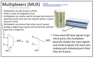
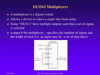
Multiplexers. Section 4.11-4.12. Topics. Multiplexers Definition Examples Verilog Modeling. Definition. A multiplexer (“mux” for short) has M data inputs and 1 output, and allows only one input to pass through that output.

Multiplexers
E N D
Presentation Transcript
Multiplexers Section 4.11-4.12
Topics • Multiplexers • Definition • Examples • Verilog Modeling
Definition • A multiplexer (“mux” for short) has M data inputs and 1 output, and allows only one input to pass through that output. • A set of additional inputs, known as select inputs, determines which input to pass through.
Railyard Switch (data inputs) (output) (selector inputs)
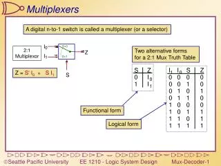
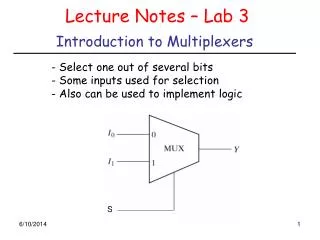
2-to-1 mux • A 2-input mux is controlled by a single control line s. • If s=0, y=a and y=b if s=1.
Verilog Modeling • Three Different Ways of Modeling a 2-to-1 MUX • Gate-level Modeling • Dataflow Modeling • Behavioral Modeling
Gate-Level Modeling A1 sb O1 N1 A2 Gate-level modeling uses instances of predefined/user-defined gates.
Module Template module module_name ( , , ) endmodule Input, output wires reg Program Body
Choosing a Module Name module module_name ( , , ) endmodule Input, output wires reg Program Body
Choosing a Module Name module module_name ( , , ) endmodule Input, output wires reg Program Body A1 sb O1 N1 A2
Output of MUX21 A1 sb O1 N1 A2
Data Flow Modeling of MUX21 Data flow modeling of a combinational logic uses a number of operators that act on operands to produce desired results. The keyword assign is used frequently in the dataflow modeling.
Behavior Modeling of MUX21 Behavioral modeling represents the digital circuits at a functional and algorithmic level. It is used mostly to describe sequential circuits, but can also be used to describe combinational circuits. Behavioral description use the keyword always. The event control expression Specifies when the statements will execute. The target output statement must be of reg data type.