Multiplexers
Multiplexers. For the rest of the day, we’ll study multiplexers, which are just as commonly used as the decoders we presented last time. Again, These serve as examples for circuit analysis and modular design. Multiplexers can implement arbitrary functions.

Multiplexers
E N D
Presentation Transcript
Multiplexers • For the rest of the day, we’ll study multiplexers, which are just as commonly used as the decoders we presented last time. Again, • These serve as examples for circuit analysis and modular design. • Multiplexers can implement arbitrary functions. • We will actually put these circuits to good use in later weeks, as building blocks for more complex designs. ©2000-2002 Howard Huang
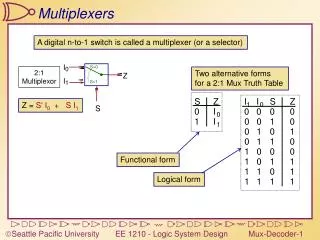
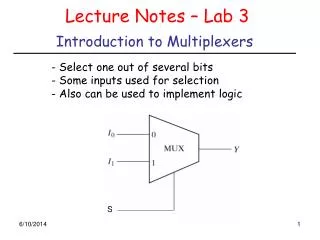
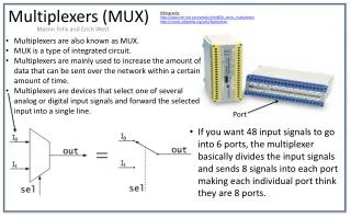
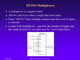
Multiplexers • A 2n-to-1 multiplexer sends one of 2n input lines to a single output line. • A multiplexer has two sets of inputs: • 2ndata input lines • n select lines, to pick one of the 2n data inputs • The mux output is a single bit, which is one of the 2n data inputs. • The simplest example is a 2-to-1 mux: • The select bit S controls which of the data bits D0-D1 is chosen: • If S=0, then D0 is the output (Q=D0). • If S=1, then D1 is the output (Q=D1). Q = S’ D0 + S D1 Additional Gates and Decoders
More truth table abbreviations • Here is a full truth table for this 2-to-1 mux, based on the equation: • Here is another kind of abbreviated truth table. • Input variables appear in the output column. • This table implies that when S=0, the output Q=D0, and when S=1 the output Q=D1. • This is a pretty close match to the equation. Q = S’ D0 + S D1 Additional Gates and Decoders
A 4-to-1 multiplexer • Here is a block diagram and abbreviated truth table for a 4-to-1 mux. • Be careful! In LogicWorks the multiplexer has an active-low EN input signal. When EN’ = 1, the mux always outputs 1. Q = S1’ S0’ D0 + S1’ S0 D1 + S1 S0’ D2 + S1 S0 D3 Additional Gates and Decoders
Implementing functions with multiplexers • Muxes can be used to implement arbitrary functions. • One way to implement a function of n variables is to use an n-to-1 mux: • For each minterm mi of the function, connect 1 to mux data input Di. Each data input corresponds to one row of the truth table. • Connect the function’s input variables to the mux select inputs. These are used to indicate a particular input combination. • For example, let’s look at f(x,y,z) = m(1,2,6,7). Additional Gates and Decoders
A more efficient way • We can actually implement f(x,y,z) = m(1,2,6,7) with just a 4-to-1 mux, instead of an 8-to-1. • Step 1: Find the truth table for the function, and group the rows into pairs. Within each pair of rows, x and y are the same, so f is a function of z only. • When xy=00, f=z • When xy=01, f=z’ • When xy=10, f=0 • When xy=11, f=1 • Step 2: Connect the first two input variables of the truth table (here, x and y) to the select bits S1 S0 of the 4-to-1 mux. • Step 3: Connect the equations above for f(z) to the data inputs D0-D3. Additional Gates and Decoders
Example: multiplexer-based adder • Let’s implement the adder carry function, C(X,Y,Z), with muxes. • There are three inputs, so we’ll need a 4-to-1 mux. • The basic setup is to connect two of the input variables (usually the first two in the truth table) to the mux select inputs. With S1=X and S0=Y, then Q=X’Y’D0 + X’YD1 + XY’D2 + XYD3 Equation for the multiplexer Additional Gates and Decoders
Multiplexer-based carry • We can set the multiplexer data inputs D0-D3, by fixing X and Y and finding equations for C in terms of just Z. When XY=00, C=0 When XY=01, C=Z When XY=10, C=Z When XY=11, C=1 C = X’ Y’ D0 + X’ Y D1 + X Y’ D2 + X Y D3 = X’ Y’ 0 + X’ Y Z + X Y’ Z + X Y 1 = X’ Y Z + X Y’ Z + XY = m(3,5,6,7) Additional Gates and Decoders
Multiplexer-based sum • Here’s the same thing, but for the sum function S(X,Y,Z). When XY=00, S=Z When XY=01, S=Z’ When XY=10, S=Z’ When XY=11, S=Z S = X’ Y’ D0 + X’ Y D1 + X Y’ D2 + X Y D3 = X’ Y’ Z + X’ Y Z’ + X Y’ Z’ + X Y Z = m(1,2,4,7) Additional Gates and Decoders
Dual multiplexer-based full adder • We need two separate 4-to-1 muxes: one for C and one for S. • But sometimes it’s convenient to think about the adder output as being a single 2-bit number, instead of as two separate functions. • A dual 4-to-1 mux gives the illusion of 2-bit data inputs and outputs. • It’s really just two 4-to-1 muxes connected together. • In LogicWorks, it’s called a “Mux-4x2 T.S.” Additional Gates and Decoders
Dual muxes in more detail • You can make a dual 4-to-1 mux by connecting two 4-to-1 muxes. (“Dual” means “two-bit values.”) • LogicWorks labels input bits xDy, which means “the xth bit of data input y.” • In the diagram on the right, we’re using S1-S0 to choose one of the following pairs of inputs: • 2D3 1D3, when S1 S0 = 11 • 2D2 1D2, when S1 S0 = 10 • 2D1 1D1, when S1 S0 = 01 • 2D0 1D0, when S1 S0 = 00 You can see how 8-way multiplexer (k-to-1) can be used to select from a set of (k) 8-bit numbers Additional Gates and Decoders
Summary • A 2n-to-1 multiplexer routes one of 2n input lines to a single output line. • Just like decoders, • Muxes are common enough to be supplied as stand-alone devices for use in modular designs. • Muxes can implement arbitrary functions. • We saw some variations of the standard multiplexer: • Smaller muxes can be combined to produce larger ones. • We can add active-low or active-high enable inputs. • As always, we use truth tables and Boolean algebra to analyze things. • Tune in tomorrow as we start to discuss how to build circuits to do arithmetic. Additional Gates and Decoders