Download
1 / 14
140 likes | 612 Vues
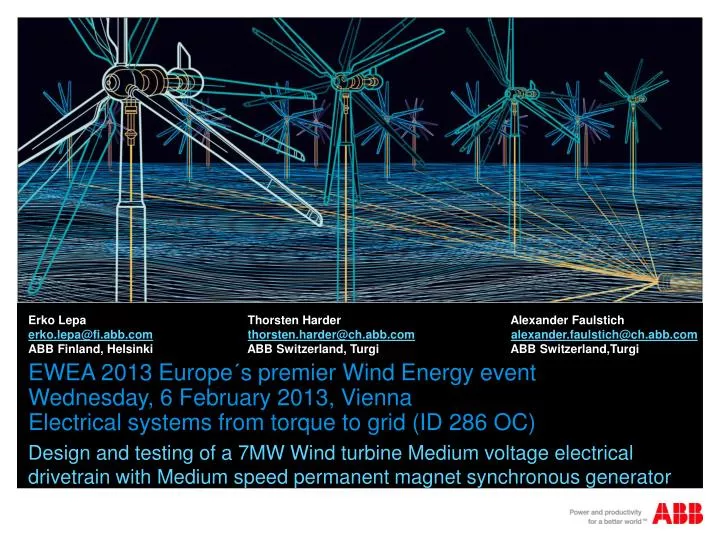
Erko Lepa Thorsten Harder Alexander Faulstich erko.lepa@fi.abb.com thorsten.harder@ch.abb.com alexander.faulstich@ch.abb.com ABB Finland, Helsinki ABB Switzerland, Turgi ABB Switzerland,Turgi .

E N D
Erko Lepa Thorsten Harder Alexander Faulstich erko.lepa@fi.abb.comthorsten.harder@ch.abb.comalexander.faulstich@ch.abb.com ABB Finland, Helsinki ABB Switzerland, Turgi ABB Switzerland,Turgi EWEA 2013 Europe´s premier Wind Energy event Wednesday, 6 February 2013, Vienna Electrical systems from torque to grid (ID 286 OC) Design and testing of a 7MW Wind turbine Medium voltage electrical drivetrain with Medium speed permanent magnet synchronous generator
Agenda • Evolution of wind turbine drives • Main concepts of megawatt range wind turbines • Benefits of Medium speed and voltage drivetrain • Design of Medium speed and voltage drivetrain • Back-to-back test
Evolution of wind turbine drivesEmerged serial production technologies HS DFIG 1.5 MW LS PMSG 2 MW MS PMSG ...5 MW PCS 6000 6 MW MS PMSG 7 MW HS PMSG 2.5 MW HS PMSG 5.7 MW PCS 1000 2 MW PCS 6000 10 MW 1900 1980 1983 1995 1997 1998 1999 2000 2002 2003 2005 2010 2012 2013 2001 High Speed: • Squirrel cage ind.gen. • Direct online Various types of multi- megawatt drivetrains (Offshore) High Speed • Doubly-fed ind.gen • - LV converter Medium Speed: • Permanent magnet • MV converters Evolution in wind Low speed: • Electrical exit. syn.gen • Permanent magnets • LV converters
Main concepts of megawatt range wind turbinesMain drivetrain concepts Low speed • Gearless DD • Turbine speed Medium speed • e.g. 1- or 2-stage geared • 100 - 500 rpm High speed • 3-stage geared • 1000 - 2000 rpm
Benefits of Medium speed and voltage drivetrain Drivetrain Efficiency = Gearbox * Generator * Converter * Transformer DD with PM DD with EE P(V)^3 MS with PM MS with EE HS concepts Annual wind distribution
Benefits of Medium speed and voltage drivetrain Voltage, Rotation speed • Medium voltage at multi-megawatt: • Small currents: Low cabling effort, lower losses • Generator design easier: Easier to manufacure, optimum terminal box • Medium speed: • Compact solution • Optimum speed, less wear • MV converters: • Reduced number of components • Robust and proven semiconductor technology Example of high current machine -> MAIN CONNECTION BOX
Design of Medium speed and voltage drivetrain Design of the Generator • Permanent Magnet Synchronous Generator • Output power: 7.35 MW • Nominal speed: 400 rpm • Nominal voltage: 3.3 kV • Shaft height: 1120 mm • V-type18 poles rotor • Pole shoes made from steel • Optimized magnet mass • Optimized cogging torque and ripple • IC86 cooling
Design of Medium speed and voltage drivetrain Design criterias of the MV Converter (PCS 6000) • Minimize Levelized cost of energy • Lowest converter losses • Highest availability (due to minimized amount of components • Lowest cabling costs/losses • Meet gird code requirements • Quick customizable design • Proven components • Flexible layout for customized footprint
Back-to-back test Summary of key results • Efficiency of generator 98.2 % (nominal point) • Temperature rise of generator in B class • No demagnetizations occured during short-circuit test • Vibrations analysed and met the expectations (worst case < 0.75 mm/s) • Optimum switching frequency determined Test Setup
Back-to-back test Stator yoke radial vibration at SF of 720 / 700 / 600 Hz 10mm/s 720Hz / 700 Hz / 600 Hz 1mm/s 0.1mm/s 10um/s 400 Hz 0 Hz 200 Hz 600 Hz 800 Hz 1000 Hz
Conclusions • Medium voltage at high turbine power is better • Medium speed concept with PMSG is compact solution • Medium speed means less wear in drive train components • Medium speed PMSG concept provide the best efficiency at nominal point
Time for Questions • Interesting links to check • http://www.youtube.com/watch?v=clKaxJALU_4 • http://www.youtube.com/watch?v=l-w10GLvZBE • http://www.youtube.com/watch?feature=endscreen&v=6LL58mUe8Ek&NR=1