
Area Target
E N D
Presentation Transcript
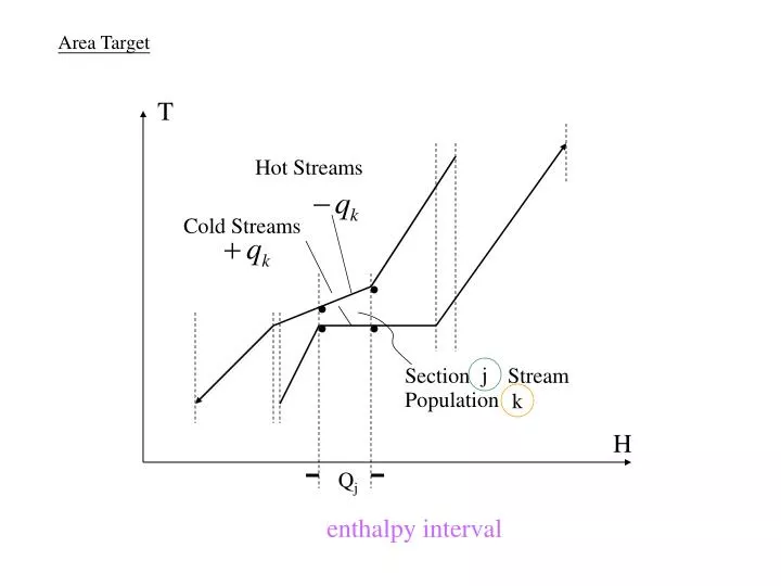
Area Target T Hot Streams Cold Streams Section Stream Population j k H Qj enthalpy interval
Townsend, D. W. and B. Linnhoff, “Surface Area Targets for Heat Exchanger Networks”, IChemE Annual Research Meeting, Bath, England (April, 1984)
T=100 T=90 CP = 0.5 CP = 2.5 CP = 1 T CP = 1 Steam CP = 6 T=80 T=75 CPH=7 T=100 T=90 T=80 T=75 CPC=14 CW H Figure B.1 within each enthalpy interval it is possible to design a network in (S - 1) matches. (From Ahmad and Simth, IChemE, ChERD, 67: 481, 1989; reproduced by permission of the Institution of Chemical Engineers.)
Table 8.1-1 Approach temperature = 10 250 240 230 220 210 200 190 180 170 160 150 140 130 120 110 100 90 Hot utility Temperature, F 1 2 + 176 + + 2 1 + j + + + 2 2 + Number of cold streams in this interval 1 1 1 + Cold utility + + 0 200 400 600 Enthalpy, 1000 Btu/hr = Hot + = Cold FIGURE 8.3-1 Tempreature-enthalpy diagram.
Hot composite Curve T (F) H (BTU/hr)103 100 0 120 80 140 180 160 280 200 480 250 530 Cold composite Curve T (F) H (103 BTU/hr) 90 60 130 180 150 360 190 600
MINIMUM HEAT TRANSFER AREA IN INTERVAL j Stream No. CP 103 qk,j 103TS TT and Type(BTU/hr.F)(BTU/hr)(F) (F) 1. Hot 1 36 176 140 2. Hot 4 144 176 140 3. Cold 3 - 60 130 150 4. Cold 6 - 120 130 150 Stream No. CP 103 qk,j 103TS TT and Type(BTU/hr.F)(BTU/hr)(F) (F) 1. Hot 1 36 176 140 2. Hot 2/3 24 176 140 31/3 120 176 140 3. Cold 1.8 - 36 130 150 1.2 - 24 130 150 4. Cold 6 - 120 130 150 1 2 3
MINIMUM HEAT TRANSFER AREA IN INTERVAL j MIN where Nj = total number of process streams in interval j MIN
Thot-cold (a) PINCH Tcold A Screening Procedure For Detection of “Bad” Matches
T A Good Match (b) Tcold A Screening Procedure For Detection of “Bad” Matches
T Two Bad Matches (c) Tcold A Screening Procedure For Detection of “Bad” Matches
(a) Temperature 1-1 Exchanger (b) Temperature 1-2 Exchanger TH1 TH1 TC2 TC2 TH2 TH2 TC1 TC1 Length Length TH1 partial cuntercurrent partial cocurrent countercurrent TC1 TC2 TC2 TH1 TC1 TH2 TH2 Q = UATLM Q =(UATLM) FT FT = f (R,P) Figure 7.7 1-1 shells approach pure countercurrent flow, whereas 1-2 shells exhibit partial countercurrent and partial cocurrent flow.
R=1 Figure 7.8
Figure 7.8 Designs with a temperature approach or small temperature cross can be accommodated in a single 1-2 shell, whereas designs with a large temperature cross become infeasible. (From Ahmad, Linnhoff, and Smith, Trans. ASME, J. Heat Transfer, 110: 340, 1988; reproduced by permission of the American Society of Mechanical Engineers.)
temperature cross large P large (a) A single 1-2 shell is infeasible. Figure 7.10 A large overall temperature cross requires shells in series to reduce the cross in individual exchangers.(From Ahmad, Linnhoff, and Smith, Trans. ASME, J. Heat Transfer, 110: 340, 1988; reproduced by permission of the American Society of Mechanical Engineers.)
temperature crosses smaller A B (b) Putting shells in series reduces the temperature cross in individual exchangers. A Figure 7.10 A large overall temperature cross requires shells in series to reduce the cross in individual exchangers.(From Ahmad, Linnhoff, and Smith, Trans. ASME, J. Heat Transfer, 110: 340, 1988; reproduced by permission of the American Society of Mechanical Engineers.) B