Download
1 / 44
440 likes | 452 Vues
This article discusses the issues and challenges in beam transverse profile measurement in the LCLS accelerator. It covers topics such as emittance measurement, stable operation, beam compression, and diagnostics for high brightness beams. Various profile monitor options like wire scanners, fluorescent screens, and OTRs are also explored.

E N D
LCLS Accelerator R+D issues: Beam Transverse Profile Measurement LCLS Commissioning Team
gey= 1.06 μm Emittance measurement at 1nC OTR screen 95% cut
Stable Operation 0.7nC
135 MeV 1.10 mm rms 14 GeV ‘Max’ Compression 14 GeV BC1 Design Compression 520 A 97 A 950 A 1.7 ps 0.89 ps 10.3 ps 14 GeV 14 GeV 135 MeV Bunch Compression (TCAV)
Slice Emittance with TCAV TAIL HEAD TAIL 1 nC, 100 A
Emittance worse after BC1 Wire scan 1nC, 1.7mm-mr Normal compression Steering in X-band, structure, poor field quality in compressor bends
Accelerator R+D topics • Various LCLS Specific issues including beam steering from the X-band RF, not of great general interest • Run uncovered some issues that ARE of general interest. • Diagnostics for high brightness beams are much more difficult that we had anticipated. • Will concentrate on the issues for beam transverse profile monitors
What makes diagnostics difficult? • High brightness beams typically have small spot sizes in diagnostic regions. • High longitudinal brightness beams can produce a host of coherent effects that confuse diagnostics. • Accelerators with high brightness beams typically need very good beam control – and therefore accurate diagnostics • Can’t use primitive tools to diagnose advanced machines
Profile Monitor Options • Wire Scanner: Scan wire through beam, measure secondary radiation • Direct calibration. Good dynamic range. Good linearity. Insensitive to longitudinal structure. Can read individual bunches in a train • Slightly invasive • Slow. Integrated profile only. Vibration problems • Fluorescent Screens: Use scintillator material in beam • Single shot image. Good sensitivity. • Invasive. Saturation for high charge densities. Material degradation over time. Powders have poor spatial resolution • OTRs: Metal foil in beam produces visible radiation at the beam “reflection” angle. • Good linearity. Good resolution. Prompt optical output, can be sued with streak cameras. • Degrades emittance but beam continues to propagate. • Poor depth of field for most installations. Coherent effects – discussed at length later. • Other: Laser wire, X-ray OTR or SLM, etc. • Tend to be Experiments, not Diagnostics
Wire Scanner Vibration Measured beam size Vs. Motor Steps / second Range is 40-140 microns With slow scanning, size was reproducible to 5 microns.
Wire Scanner Vibration is not a new problem. Scan from old SLC wires (1980s) LI02 wire scanner, 20um/step 119 micron width LI02 wire scanner, 15um/step 149 micron width
Wire Scanner Vibration Fixes • Increase lowest resonance frequency above step frequency • Make structure stiffer or smaller: Resonant frequency only goes as square root of stiffness. • Increase step frequency above low order mechanical resonances • Gear reducers – should work, but reduce maximum speed • Non-stepping driver: DC servo motor, micro-stepping, direct piezoelectric drive. • More complexity, problems with radiation and long cables. • Move beam not wire • Works if you understand the optics, but makes wire scan invasive. • Wire scanners can be made to work – but don’t ignore the engineering issues: Easy to get it wrong.
Why we need screens: A wire-scanner like measurement would not have shown this! Pathological beam shape that would Not be apparent on wires
Screen Saturation Does good data on saturation exist? Saturation estimated at 0.04pC/um2 1nC in 50um spot is 10X this density A. Murokh et al, PAC2001
Can we fix saturation in software? • Expect saturation to have the form y=1-e-x with x the beam intensity, y the fluorescence intensity. • Can in principal fix with yf=-ln(1-y) • Of course this will amplify noise for high saturation levels
Simulated Gaussian Beam Spots – Saturation Correction 5X saturation Charge Can probably make a reasonable correction for a factor of ~5 above saturation. (simulation assumes 100:1 signal / noise, 1000:1 dynamic range for camera Spot size
OTR Emission • Each electron emits ~ α (1/137) photons from ~DC to γωp in the forward direction, and DC to ωp in the “Reflected” direction .where ωp is the plasma frequency ~100nm (20eV) for typical metals. • Emission is prompt • For CW beam, each electron emits incoherently, power scales as Ne • For wavelengths long compared to the bunch length, electrons will radiate coherently, power scales as Ne2 • For 1nC beam, for wavelengths >> bunch length, coherent effects can increase output power by >109 • If there is modulation on the electron beam at optical frequencies, this will produce additional coherent emission. • With a typical 1mm pulse length, 1nC, we have ~106 electrons in an optical wavelength. • Density modulation of ~10-3 at optical wavelengths will substantially increase emission. • Longitudinal coherence causes longitudinal structure to distort transverse profiles.
LCLS Energy Spread 157pC Time Energy Transverse cavity on, minimum energy spread at spectrometer (135MeV) is ~5KV Small energy spread allows preservation and amplification of short wavelength current modulation
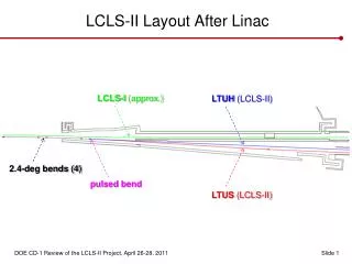
LCLS Injector Gun S-band Accelerator OTR 11 X-band Accelerator OTR 12 “Dog leg Bend” QB Bunch Compressor 1 (shown straight)
Coherent OTR effects in LCLS • In “Dog leg 1”, the first bend, we can adjust the residual dispersion with quad “QB”. • Look at images on OTR screen after dog leg • Bunch compressor magnets ON • RF on crest (no compression)
Beam size distortions in OTR12 OTR12 sum signal as QB is varied. BC1 off, L1X, L1S on crest. Y beam size Varies with observed intensity
Effect is in the OTR, not the camera – vary optical attenuation OTR11 integrated signal, Vary QB Filter 2 in. Width 0.094 +/- .002 Amplification 2.43 OTR11 integrated signal, Vary QB No filter. Width 0.115 +/- .003 Amplification 1.86
OTR12 signal with OTR11 in or out L1S, L1X on crest BC1 off, Filter 1+2 Fit to A*q + B*q2/(1+q4/c4) incoherent Coherent Modulation decreased (space charge?) for higher currents (VERY APPROXIMATE)
OTR12 effect is OTR, not camera Different optical attenuations
OTR12 Sum vs. QM 13 Can have significant effects From other quads. OTR12 QM 13 To Dump From BC1
Effects at high compression: Litrack simulation, 200pc, maximum compression 12 fs, FWHM P. Emma Might expect significant fraction of the beam within one optical wavelength: Strong coherent effects
OTR12 optical signal vs. Phase 200pc. High compression Typical signal non-compressed 3 MCounts, Maximum at compression >100MCounts and saturated.
100GHz, 300GHz and Optical signals Bunch length diodes show maximum compression at same phase as maximum OTR. OTR produces unstable transverse beam measurements Wire Scan 300GHz 100GHz OTR Profile – multi shot Optical OTR12 projections (COTR? CSR breakup?)
Why Doughnuts? H. Loos
COTR Doughnuts • Radial polarization acts like gradient operator • For Gaussian beam gives doughnut H. Loos
Other OTR effects – Synchrotron radiation OTR11 OTR beam exists at “reflection” angle – so foil will also reflect SR Can add optical vertical polarizer to suppress synchrotron light. OTR11 ( in BC1) OTR4 in DL1
Gallery of Beam Breakup / coherent Effects. All at same (extreme compression, 1nC) settings
Uses for COTR • With maximum bunching in BC2, it may be possible to generate a substantial amount of very broadband (DC-light), power in a few femtosecond pulse, synchronized with the LCLS beam. • Is this useful as an experimental source, optical trigger, etc? • If we modulate the beam at optical wavelengths (laser / undulator), can detect optical modulation downstream on any OTR. Measure propagation of high freuqency structure.
COTR Implications For Other Diagnostics • Coherent effects will distort measurements from any “prompt” light emission: • ODR, Cherenkov, Synchrotron, etc. • Coherent effects could distort fluorescent screen measurements • Coherent OTR or Cherenkov in the UV could excite fluorescence. • Directly excitation of fluorescence from the coherent high frequency components in the electric field. • COTR can be brighter than scintillation, need gated camera to separate. • Thermal measurements may be OK • Coherent emission could add to ionization energy loss. • In principal I2R heating depends on bunch length and could become significant compared with ionization energy loss • Probably not a problem for our beam parameters, but needs study • Not clear how to image a high resolution thermal source.
OTR / Profile monitor Questions • What is the spectrum of the OTR under different beam conditions • What is the total OTR optical power when we see strong COTR • Understand longitudinally coherent, spatially incoherent OTR
What to do for Beam Imaging • OTR operating in near UV • Will work if we don’t have beam modulation at short wavelengths. • Can go as far as ~200nm without exotic windows, cameras. • But – will problem be worse after BC2? • Calculations do not rule out coherence at wavelengths as short as 100nm in the LCLS. • X-ray imaging • Short wavelengths immune to coherent effects • X-ray generation forward directed. Difficult to set up optics. • More like an “experiment” than a diagnostic. • Wire scanners • Work with good engineering • Mult-shot profiles only. • Laser Heater • The LCLS plans to use an inverse FEL to increase the energy spread of the beam to reduce CSR • Should dramatically reduce COTR problems • Don’t like to rely on this – nice to be able to diagnose the beam without the heater.