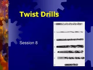
Twist Drills
Twist Drills. Session 8. Twist Drills. End-cutting tools Used to produce holes in most types of materials Two helical grooves, or flutes, are cut lengthwise around body of drill Provide cutting edges and space for cuttings to escape during drilling process. Twist Drill Parts.

Twist Drills
E N D
Presentation Transcript
Twist Drills Session 8
Twist Drills • End-cutting tools • Used to produce holes in most types of materials • Two helical grooves, or flutes, are cut lengthwise around body of drill • Provide cutting edges and space for cuttings to escape during drilling process
Twist Drill Parts • Most made of high-speed steel • Replaced carbon-steel drills for two reasons • Can be operated at double the cutting speed • Cutting edge lasts longer • Stamped with letters H.S or H.S.S. • Carbide-tipped drills • Speeds for production have increased up to 300% over high-speed drills
Point Body Shank Three Main Partsof a Drill
Drill Shank • Straight-shank drills • Held in drill chuck • Up to ½ in. in diameter • Tapered-shank drills • Fit into internal taper of drill press spindle • Tang provided on end to prevent drill from slipping
Drill Body • Portion of drill between shank and point • Consists of number of parts for cutting • Flutes • Two or more helical grooves cut around body of drill • Form cutting edges, admit cutting fluid, allow chips to escape hole • Body Clearance • Undercut portion of body between margin and flutes
Drill Body • Margin • Narrow, raised section on body of drill • Extends entire length of flutes • Provides full size to drill body and edges • Web • Thin partition in center of drill, extends full length of flutes • Forms chisel edge at cutting end of drill
Drill Point • Consists of chisel edge, lips, lip clearance, and heel • Chisel edge • Chisel-shaped portion of drill point • Lips • Cutting edges formed by intersection of flutes • Must be of equal length and have same angle • So drill run true and not cut hole larger than drill
Lip Clearance • The relief ground on point of drill extending from cutting lips back to the heel
Drill Point Characteristics The use of various point angles and lipclearances, in conjunction with thinningof the drill web, will allow: • Control size, quality and straightness of drilled hole • Control size, shape and formation of chip • Control chip flow up flutes • Increase strength of drill's cutting edges
Drill Point Characteristics • Reduce rate of wear at cutting edges • Reduce amount of drilling pressure required • Control amount of burr produced • Reduce amount of heat generated • Permit use of various speeds and feeds for more efficient drilling
Conventional Point (118º) • Most commonly used drill point • Gives satisfactory results for most general-purpose drilling • Lip clearance of 8º to 12º for best results • Too much weakens cuttingedge and causes drill to chip • Too little results in use ofheavy drilling pressure
Long Angle Point 60º - 90º • Used on low helix drills for drilling of nonferrous metals, soft cast irons, plastics, fibers, and wood • Lip clearance generally from 12º to 15º • Flat may be ground on face of lips to prevent drill from drawing itself into the soft material
Flat Angle Point 135º -150º • Used to drill hard and tough materials • Lip clearance on flat angle point drills only 6º to 8º to provide as much support as possible for cutting edges • Shorter cutting edge tends to reduce friction and heat during drilling
Four Systems of Drill Sizes • Fractional • Number • Letter • Millimeter (Metric)
Four Systems of Drill Sizes • Fractional • Range from 1/64 to 4 in. (steps of 1/64th )
Four Systems of Drill Sizes • Number • Range from #1 (.228 in.) to #97 (.0059 in.)
Four Systems of Drill Sizes • Letter • Range from A to Z (A = .234 in., Z = .413 in.)
Four Systems of Drill Sizes • Millimeter (Metric) • Straight-shank standard (0.5 to 20 mm)
Types of Drills • Wide variety manufactured to suit specific drilling operations and materials • Design of drills vary • Number and width of flutes • Amount of helix or rake angle of flutes • Shape of land or margin • Shape of flute: straight or helical • Whether helix is right-hand or left-hand
Twist Drills • Manufactured from four main materials • Carbon-steel drills • High-speed steel drills – Uncoated • High-speed steel drills – Coated • High Cobalt Content • Cemented-carbide drills
Twist Drills • Carbon-steel drills • Used in hobby shops not for machine shop work • Lowest cost of all drills • Cutting edges wear down quickly
Twist Drills • High-speed steel drills - Uncoated • Used extensively in machine shop work • Replaced High Carbon Steel Drills • Cutting edges withstand more heat and wear • Most commonly used
Twist Drills • High-speed steel drills - Coated • Used extensively in machine shop work • Supplements uncoated High Speed Steel Drills • Cutting edges withstand much more heat and wear Black Oxide Titanium Nitride
Twist Drills • High Cobalt High-Speed Steel drills • Used in machine shop work • 5% Cobalt allows cutting edges to withstand more heat and wear
Twist Drills • Cemented-carbide drills • Operated at high speeds, withstand higher heat, and can drill hard materials • Carbide Tipped • Solid Carbide
General-Purpose Drill • Has two Helical flutes • Designed to perform well on wide variety of materials, equipment and job conditions • Can be made to suit different conditions and materials by varying point angle, speeds and feeds • Straight-shank drills called general-purpose jobbers length drills
Low-Helix Drill • Developed primarily to drill brass and thin materials • Used to drill shallow holes in some aluminum and magnesium alloys • Can remove large volume of chips formed by high rates of penetration
High-Helix Drills • Designed for drilling deep holes in aluminum, copper, die-cast material, and other metals • Material where chips have tendency to jam • High helix angle (35º to 45º) • Wider flutes assist in clearing chips from hole
Core Drill • Three or four flutes • Used to enlarge cored, drilled, or punched holes • Produced in sizes from ¼ to 3 in.
Oil Hole Drills • Have one or two oil holes running from shank to cutting point • Compressed air, oil, or cutting fluid can be forced through when deep holes being drilled • Cutting fluid cools drill's cutting edges and flushes chips out of hole
Straight-Fluted Drills • Recommended for drilling operations on soft materials such as brass, bronze, copper and various types of plastic • Straight flute prevents drill from drawing itself into material while cutting
Deep Hole (Gun) Drills • Used for producing holes from approximately 3/8 to 3 in. in diameter and as deep as 20 feet • Consists of round, tubular stem, on end is fastened flat, two-fluted drilling insert • Cutting fluid forced through center of stem to flush chips from hole
Spade Drills • Cutting end is flat blade with two cutting lips • Easily replaced or sharpened • Available in wide range of sizes • Micro to 12 inch diameter
Hard-Steel Drill • Used for drilling hardened steel • Made from heat-resistant alloy • As brought into contact with workpiece, fluted, triangular point softens metal by friction and then removes softened metal
Step Drills • Used to drill and countersink or drill and counterbore different sizes of holes in one operation • Usually has two or more diameters • Each size or step separated by square or angular shoulder
Saw-Type Hole Cutter • Cylindrical-diameter cutter with twist drill in center to provide guide for cutting teeth on hole cutter • Made in various diameters • Used for drillingholes in thin materials • Little burr produced
Procedure to Grind a Drill • Wear approved safety glasses • Check grinding wheel and dress it to sharpen and/or straighten wheel face • Adjust grinder tool rest so it is within .060 in. of wheel face • Examine drill point and margins for wear
Hold drill near point with one hand, other hand hold shank of drill slightly lower than point • Move drill so it is approximately 59º to face of grinding wheel • Hold lip or cutting edge of drill parallel to grinder toolrest • Bring lip of drill against grinding wheel and slowly lower drill shank
Drilling Facts and Problems • Excessive speed • Excessive clearance • Excessive feed • Insufficient clearance • Cutting lips with unequal angles • Cutting lips with unequal in length • Loading and galling
Excessive speed will cause wear at outer cornersof drill. This permits fewer regrinds of drill dueto amount of stock to be removed in reconditioning.Discoloration is warning sign of excess speed.
Excessive clearance results in lack of supportbehind cutting edge with quick dulling and poortool life. Despite initial free cutting action. Clearance angle behind cutting lip for generalpurposes is 8º to 12º.
Excessive feed sets up abnormal end thrust, which causes breakdown of chisel point and cutting lips. Failure induced by this cause will be broken or split drill.
Insufficient clearance causes the drill to rub behind the cutting edge. It will make the drill work hard, generate heat, and increase end thrust. This results in poor holes and drill breakage.
The web is the tapered central portion of thebody that joins the lands.
Cutting lips with unequal angles will cause onecutting edge to work harder than the other. Thiscauses torsion strain, bellmouth holes, rapid dulling, and poor tool life.
Cutting lips unequal in length cause chisel point to be off center axis and will drill holes oversize by approximately twice the amount of eccentricity.
Loading and galling is caused by poor chipremoval with insufficientdissipation of heat so that material anneals itself to the cutting edge and flute. This condition frequentlyresults from using wrong drills for the job or inadequate cutting fluid application.
Characteristics of a Properly Ground Drill • Length of both cutting lips equal • Angle of both cutting lips be the same • Lips should be free from nicks or wear • No sign of wear on margin Note: Resharpen drill if it does not meet all of these requirements.