Download
1 / 44
440 likes | 503 Vues
Learn the concepts of Jacobian matrix and linear & angular velocities in robotics. Explore different methods for velocity propagation and understand the relationship between joint angles, end effector velocities, and torques. Instructor: Jacob Rosen, UCLA.

E N D
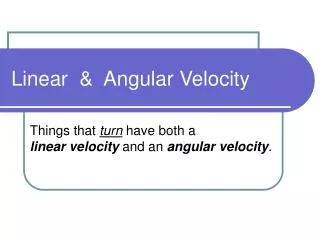
Linear and Angular Velocities 2/4 Instructor: Jacob Rosen Advanced Robotic - MAE 263D - Department of Mechanical & Aerospace Engineering - UCLA
Jacobian Matrix - Calculation Methods Iterative Propagation (Velocities or Forces / Torques) Differentiation the Forward Kinematics Eqs. Jacobian Matrix Instructor: Jacob Rosen Advanced Robotic - MAE 263D - Department of Mechanical & Aerospace Engineering - UCLA
Jacobian Matrix - Introduction • In the field of robotics the Jacobian matrix describe the relationship between the joint angle rates ( ) and the translation and rotation velocities of the end effector ( ). This relationship is given by: • In addition to the velocity relationship, we are also interested in developing a relationship between the robot joint torques ( ) and the forces and moments ( ) at the robot end effector (Static Conditions). This relationship is given by: Instructor: Jacob Rosen Advanced Robotic - MAE 263D - Department of Mechanical & Aerospace Engineering - UCLA
Velocity Propagation – Link / Joint Abstraction Instructor: Jacob Rosen Advanced Robotic - MAE 263D - Department of Mechanical & Aerospace Engineering - UCLA
Velocity Propagation – Intuitive Explanation • Three Actions • The origin of frame B moves as a function of time with respect to the origin of frame A • Point Q moves with respect to frame B • Frame B rotates with respect to frame A along an axis defined by Instructor: Jacob Rosen Advanced Robotic - MAE 263D - Department of Mechanical & Aerospace Engineering - UCLA
Velocity Propagation – Intuitive Explanation Instructor: Jacob Rosen Advanced Robotic - MAE 263D - Department of Mechanical & Aerospace Engineering - UCLA
Central Topic - Simultaneous Linear and Rotational Velocity • Vector Form • Matrix Form Instructor: Jacob Rosen Advanced Robotic - MAE 263D - Department of Mechanical & Aerospace Engineering - UCLA
Summary – Changing Frame of Representation • Linear and Rotational Velocity • Vector Form • Matrix Form • Angular Velocity • Vector Form • Matrix Form Instructor: Jacob Rosen Advanced Robotic - MAE 263D - Department of Mechanical & Aerospace Engineering - UCLA
Definitions - Linear Velocity • Linear velocity - The instantaneous rate of change in linear position of a point relative to some frame. Q Instructor: Jacob Rosen Advanced Robotic - MAE 263D - Department of Mechanical & Aerospace Engineering - UCLA
Definitions - Linear Velocity • The position of point Q in frame {A} is represented by the linear position vector • The velocity of a point Q relative to frame {A} is represented by thelinear velocity vector Instructor: Jacob Rosen Advanced Robotic - MAE 263D - Department of Mechanical & Aerospace Engineering - UCLA
Linear Velocity - Rigid Body • Given: Consider a frame {B} attached to a rigid body whereas frame {A} is fixed. The orientation of frame {A} with respect to frame {B} is not changing as a function of time • Problem: describe the motion of of the vector relative to frame {A} • Solution: Frame {B} is located relative to frame {A} by a position vector and the rotation matrix (assume that the orientation is not changing in time ) expressing both components of the velocity in terms of frame {A} gives Q Instructor: Jacob Rosen Advanced Robotic - MAE 263D - Department of Mechanical & Aerospace Engineering - UCLA
Linear Velocity – Translation Instructor: Jacob Rosen Advanced Robotic - MAE 263D - Department of Mechanical & Aerospace Engineering - UCLA
Linear Velocity – Translation Instructor: Jacob Rosen Advanced Robotic - MAE 263D - Department of Mechanical & Aerospace Engineering - UCLA
Linear & Angular Velocities - Frames • When describing the velocity (linear or angular) of an object, there are two important frames that are being used: • Represented Frame (Reference Frame): This is the frame used to represent (express) the object’s velocity. • Computed Frame This is the frame in which the velocity is measured (differentiate the position). Instructor: Jacob Rosen Advanced Robotic - MAE 263D - Department of Mechanical & Aerospace Engineering - UCLA
Frame - Velocity • As with any vector, a velocity vector may be described in terms of any frame, and this frame of reference is noted with a leading superscript. • A velocity vector computed in frame {B} and represented in frame {A} would be written Represented (Reference Frame) Computed (Measured) Instructor: Jacob Rosen Advanced Robotic - MAE 263D - Department of Mechanical & Aerospace Engineering - UCLA
Frame - Linear Velocity • We can always remove the outer, leading superscript by explicitly including the rotation matrix which accomplishes the change in the reference frame • Note that in the general case because may be time-verging • If the calculated velocity is written in terms of of the frame of differentiationthe result could be indicated by a single leading superscript. • In a similar fashion when the angular velocity is expresses and measured as a vector Instructor: Jacob Rosen Advanced Robotic - MAE 263D - Department of Mechanical & Aerospace Engineering - UCLA
C y B x D A {C} y x {W} E F Frames - Linear Velocity - Example • Given: The driver of the car maintains a speed of 100 km/h (as shown to the driver by the car’s speedometer). • Problem: Express the velocities in each section of the road A, B, C, D, E, F where {C} - Car frame, and {W} - World frame Represented (Reference Frame) Computed (Measured) Object Frame Instructor: Jacob Rosen Advanced Robotic - MAE 263D - Department of Mechanical & Aerospace Engineering - UCLA
C B D A E F Models of Robot Manipulation - EE 543 - Department of Electrical Engineering -University of Washington
Frames - Linear Velocity - Example Instructor: Jacob Rosen Advanced Robotic - MAE 263D - Department of Mechanical & Aerospace Engineering - UCLA
Frames - Linear Velocity - Example • is not time-varying (in this example) Instructor: Jacob Rosen Advanced Robotic - MAE 263D - Department of Mechanical & Aerospace Engineering - UCLA
Frames - Linear Velocity - Example C C C C C C B B B B B B D D D D D D A A A A A A E E E E E E Instructor: Jacob Rosen Advanced Robotic - MAE 263D - Department of Mechanical & Aerospace Engineering - UCLA
{A} {B} {C} Linear Velocity - Free Vector • Linear velocity vectors are insensitive to shifts in origin. • Consider the following example: • The velocity of the object in {C} relative to both {A} and {B} is the same, that is • As long as {A} and {B} remain fixed relative to each other (translational but not rotational), then the velocity vector remains unchanged (that is, a free vector). Instructor: Jacob Rosen Advanced Robotic - MAE 263D - Department of Mechanical & Aerospace Engineering - UCLA
Angular Velocity - Rigid Body - Intuitive Approach Instructor: Jacob Rosen Advanced Robotic - MAE 263D - Department of Mechanical & Aerospace Engineering - UCLA
Angular Velocity - Rigid Body • Given: Consider a frame {B} attached to a rigid body whereas frame {A} is fixed. The vector is constant as view from frame {B} • Problem: describe the velocity of the vector representing the the point Q relative to frame {A} • Solution: Even though the vector is constant as view from frame {B} it is clear that point Q will have a velocity as seen from frame {A} due to the rotational velocity Q Instructor: Jacob Rosen Advanced Robotic - MAE 263D - Department of Mechanical & Aerospace Engineering - UCLA
Angular Velocity - Rigid Body - Intuitive Approach Instructor: Jacob Rosen Advanced Robotic - MAE 263D - Department of Mechanical & Aerospace Engineering - UCLA
Angular Velocity - Rigid Body - Intuitive Approach • The figure shows to instants of time as the vector rotates around This is what an observer in frame {A} would observe. • The Magnitude of the differential change is • Using a vector cross product we get Instructor: Jacob Rosen Advanced Robotic - MAE 263D - Department of Mechanical & Aerospace Engineering - UCLA
Angular Velocity - Rigid Body - Intuitive Approach • Rotation in 2D Instructor: Jacob Rosen Advanced Robotic - MAE 263D - Department of Mechanical & Aerospace Engineering - UCLA
Angular Velocity - Rigid Body - Intuitive Approach • In the general case, the vector Q may also be changing with respect to the frame {B}. Adding this component we get. • Using the rotation matrix to remove the dual-superscript, and since the description of at any instance is we get Instructor: Jacob Rosen Advanced Robotic - MAE 263D - Department of Mechanical & Aerospace Engineering - UCLA
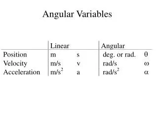
Definitions - Angular Velocity • Angular Velocity: The instantaneous rate of change in the orientation of one frame relative to another. Point - 1D Linear Velocity Plane - 2D / Body - 3D Angular Velocity Plane - 2D / Body - 3D Instructor: Jacob Rosen Advanced Robotic - MAE 263D - Department of Mechanical & Aerospace Engineering - UCLA
Definitions - Angular Velocity • Just as there are many ways to represent orientation (Euler Angles, Roll-Pitch-Yaw Angles, Rotation Matrices, etc.) there are also many ways to represent the rate of change in orientation. • The angular velocity vector is convenient to use because it has an easy to grasp physical meaning. However, the matrix form is useful when performing algebraic manipulations. Angular Velocity Representation Angular Velocity Vector Angular Velocity Matrix Instructor: Jacob Rosen Advanced Robotic - MAE 263D - Department of Mechanical & Aerospace Engineering - UCLA
Definitions - Angular Velocity - Vector • Angular Velocity Vector: A vector whose direction is the instantaneous axis of rotation of one frame relative to another and whose magnitude is the rate of rotation about that axis. • The angular velocity vector describes the instantaneous change of rotation of frame {B} relative to frame {A} Instructor: Jacob Rosen Advanced Robotic - MAE 263D - Department of Mechanical & Aerospace Engineering - UCLA
Definitions - Angular Velocity - Matrix • The rotation matrix ( ) defines the orientation of frame {B} relative to frame {A}. Specifically, the columns of are the unit vectors of {B} represented in {A}. • If we look at the derivative of the rotation matrix, the columns will be the velocity of each unit vector of {B} relative to {A}: Instructor: Jacob Rosen Advanced Robotic - MAE 263D - Department of Mechanical & Aerospace Engineering - UCLA
Definitions - Angular Velocity - Matrix • The relationship between the rotation matrix and the derivative of the rotation matrix can be expressed as follows: • where is defined as the angular velocity matrix Instructor: Jacob Rosen Advanced Robotic - MAE 263D - Department of Mechanical & Aerospace Engineering - UCLA
Angular Velocity - Matrix & Vector Forms Matrix Form Vector Form Definition Multiply by Constant Multiply by Vector Multiply by Matrix Instructor: Jacob Rosen Advanced Robotic - MAE 263D - Department of Mechanical & Aerospace Engineering - UCLA
Simultaneous Linear and Rotational Velocity - Vector Versus Matrix Representation Vector Form Matrix Form Instructor: Jacob Rosen Advanced Robotic - MAE 263D - Department of Mechanical & Aerospace Engineering - UCLA
Simultaneous Linear and Rotational Velocity • The final results for the derivative of a vector in a moving frame (linear and rotation velocities) as seen from a stationary frame • Vector Form • Matrix Form Instructor: Jacob Rosen Advanced Robotic - MAE 263D - Department of Mechanical & Aerospace Engineering - UCLA
Changing Frame of Representation - Linear Velocity • We have already used the homogeneous transform matrix to compute the location of position vectors in other frames: • To compute the relationship between velocity vectors in different frames, we will take the derivative: Instructor: Jacob Rosen Advanced Robotic - MAE 263D - Department of Mechanical & Aerospace Engineering - UCLA
Changing Frame of Representation - Linear Velocity • Recall that • so that the derivative is Instructor: Jacob Rosen Advanced Robotic - MAE 263D - Department of Mechanical & Aerospace Engineering - UCLA
Changing Frame of Representation - Linear Velocity • Substitute the previous results into the original equation we get • This expression is equivalent to the following three-part expression: Instructor: Jacob Rosen Advanced Robotic - MAE 263D - Department of Mechanical & Aerospace Engineering - UCLA
Changing Frame of Representation - Linear Velocity • Converting from matrix to vector form yields Instructor: Jacob Rosen Advanced Robotic - MAE 263D - Department of Mechanical & Aerospace Engineering - UCLA
Angular Velocity • Frame {C} is rotated around frame {B} by • Frame {B} is rotated around frame {A} by • Given • Find Instructor: Jacob Rosen Advanced Robotic - MAE 263D - Department of Mechanical & Aerospace Engineering - UCLA
Changing Frame of Representation - Angular Velocity • We use rotation matrices to represent angular position so that we can compute the angular position of {C} in {A} if we know the angular position of {C} in {B} and {B} in {A} by • To derive the relationship describing how angular velocity propagates between frames, we will take the derivative • Substituting the angular velocity matrixes • we find Instructor: Jacob Rosen Advanced Robotic - MAE 263D - Department of Mechanical & Aerospace Engineering - UCLA
Changing Frame of Representation - Angular Velocity • Post-multiplying both sides by ,which for rotation matrices, is equivalent to • The above equation provides the relationship for changing the frame of representation of angular velocity matrices. • The vector form is given by • To summarize, the angular velocities of frames may be added as long as they are expressed in the same frame. Instructor: Jacob Rosen Advanced Robotic - MAE 263D - Department of Mechanical & Aerospace Engineering - UCLA
Summary – Changing Frame of Representation • Linear and Rotational Velocity • Vector Form • Matrix Form • Angular Velocity • Vector Form • Matrix Form Instructor: Jacob Rosen Advanced Robotic - MAE 263D - Department of Mechanical & Aerospace Engineering - UCLA