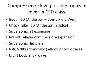

Understanding Compressible Flow: Equations & Applications
E N D
Presentation Transcript
Goals • Describe how compressible flow differs from incompressible flow • Define criteria for situations in which compressible flow can be treated as incompressible • Provide example of situation in which compressibility cannot be neglected • Write basic equations for compressible flow • Describe a shape in which a compressible fluid can be accelerated to velocities above speed of sound (supersonic flow)
Basic Equations Five changeable quantities are important in compressible flow: • Cross-sectional area, S • Velocity, u • Pressure, p • Density, r • Temperature, T
Basic Equations Restrict focus to those systems in which properties are only changing in flow direction. Generally, cross-sectional area S is specified as a function of x. (S=S(x)) Need four equations to describe the other four variables.
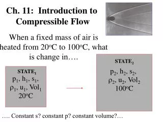
Basic Equations • Mass Balance relates r, u, S • Mechanical Energy Balance relates r, u, S, p • Equation of State relates T, p,r • Total Energy Balance relates Q, T What is different about compressible flow? r, u, p all change with position. Need to use differential form of equations.
Mass Balance In differential form Divide both sides by ruS
Mechanical Energy Balance Differentiate and assume Ŵ = 0
Viscous Dissipation For a short section of pipe: Assumes only wall shear (no fittings)
Equation of State For simplicity it is assumed that z is either 1 (ideal) or a constant Volume: Density:
Total Energy Balance For gases thermodynamics allows a better calculation of the heat transfer Q and changes in internal energy. These were terms that were previously included in the viscous dissipation term. The temperature of a flowing gas depends on: • Rate of heat transfer Q from environment. • Rate of viscous dissipation (significant in compressors). Included in work term Ŵc • Thermodynamic changes H.
Total Energy Balance Q is the rate of heat addition along the entire length of the channel and Ŵc is the total rate of energy input into the system and includes efficiency to account for viscous dissipation. For Ŵc to be in the correct units use:
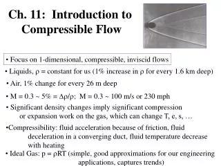
Compressible vs. Incompressible When can simpler incompressible equations be used? • Density change is not significant (<10%) • Fans, airflow through packed beds Mach number is a measure of the importance of density changes for compressible fluids. Rule of Thumb: NMa < 0.3 assume incompressible
Isentropic Flow Adiabatic (Q = 0) and Reversible Isentropic (ΔS = 0) Venturi meter, Rocket propulsion
Adiabatic Flow Adiabatic (Q = 0), Frictional Mathematically more difficult Short Insulated Pipes
Isothermal Flow Isothermal, Frictional Long Uninsulated Pipes
Goals • Describe equations useful for analyzing isothermal, compressible flow through a constant diameter pipe. • Describe how Mach number and L are related for flow in a constant diameter pipe. • Use equations for isothermal flow to compute the flow rate of compressible fluids in constant diameter pipes.
Isothermal FlowConstant Diameter Pipe P1,r1 P2,r2 Goal is to analyze the friction section. Flow through pipes is irreversible so viscous dissipation is important.
Mass Balance S is constant Mass velocity constant Differential Balance
Mechanical Energy Balance turbulent horizontal no compressor
Total Energy Balance turbulent horizontal isothermal no work Note: This indicates that there must be heat transfer because dT = 0. This is the heat required to keep T constant.
Equation of State isothermal
Isothermal Flow Combining Mass, MEB and EOS Assume friction factor f is constant and integrate:
Isothermal Flow P2,r2 P1,r1
Isothermal Flow For a fixed P1 this expression has a maximum at:
Maximum Flow Ernst Mach (1838-1916) Thus for a constant cross-section pipe the maximum obtainable velocity is Mach one for any receiver pressure. This is said to be choked flow.
“Choked” Flow PCritical Vsonic GMax P1 Unattainable Flows Sonic Velocity Attainable Flows G P1 PCritical
Example Problem (maximum flow) An astronaut is receiving breathing oxygen at 10 C from his space capsule through a 7 meter long, 1.7 cm diameter, hose. The capsule supply pressure is 200 kPa and the suit pressure is 100 kPa. What is the flow rate of the oxygen to the suit ? If the hose breaks off at the suit, what is the flow rate of oxygen ? What is the pressure at the end of the hose ? The hose is “smooth”.
Calculation Approach (subsonic flow) Given P1, P2, and T Assume subsonic flow at the end of the pipe. Calculate NRE Assume G Calculate f Calculate G Iterate Calculate V at end of pipe If V > V sonic - flow is unattainable - got to next page Calculate V sonic at end of pipe
Calculation Approach (sonic flow) Given P1, P2, and T Assume sonic flow at the end of the pipe. Assume FDTF Assume GMax Calculate f Calculate GMax Iterate Check FDTF assumption Calculate P2 (sonic) Calculate NRE If P2 (sonic) > P2 - flow is sonic at end of pipe and G = GMax
10 Minute Problem Nitrogen (m = 0.02 cP ) is fed from a high pressure cylinder through ¼ in. ID stainless steel tubing ( k = 0.00015 ft) to an experimental unit. The line ruptures at a point 10 ft. from the cylinder. If the pressure in the nitrogen in the cylinder is 3000 psig and the temperature is constant at 70 F, what is the mass flow rate of the gas through the line and the pressure in the tubing at the point of the break ? 10 ft P = 3014 psia P = 1 atm
Isentropic Flow of Inviscid Fluid In this case The mass balance and MEB are the same as that for the isothermal case. Now though the total energy balance will give a relation between the velocity and temperature
Total Energy Balance horizontal adiabatic 1
Equation of State Given the normal equation of state, the TEB, MEB, and the thermodynamic relation Cp – Cv = zR/M, isentropic flow gives the following useful values.
Useful Relationships Given the normal equation of state, the TEB, MEB, and the thermodynamic relation Cp – Cv = zR/M, isentropic flow gives the following useful values.
From Mechanical Energy Balance or Integrating u ↔ p
Isentropic Flow u ↔ T u ↔r
Velocity, NMa, and Stagnation For isentropic flow the definition of the speed of sound is: It is also convenient to express the relationships in terms of a reference state where u0 = 0. This is called the stagnation condition (u0 = 0) and P0 and T0 are the stagnation pressure and temperature.
Velocity – Mach Relationships The previous relationships now become: and
Cross-Sectional Areafor Sonic Flow Application of the continuity (mass balance) equation gives: S* is a useful quantity. It is the cross-sectional area that would give sonic velocity (NMa = 1).
Summary of Equations for Isentropic Flow p0, T0, r0, are at the stagnant (reservoir) conditions. These ratios are often tabulated versus NMa for air (g = 1.4). One must use the equations for gases with g ≠ 1.4.
Maximum Mass Flow Rate Since the maximum velocity at the throat is NMa = 1, there is a maximum flow rate: Increase flow by making throat larger, increasing stagnation pressure, or decrease stagnation temperature. Receiver conditions do not affect mass flow rate.
Drug Injection via Converging / Diverging Nozzle Supersonic jet Helium cylinder Contour Shock Tube Powdered drug cassette
Shock Behavior Po Pt PR Isentropic Paths PR = Pc PR = Pe PR = Pf Non-Isentropic Paths Pe< PR < Pf Sonic Flow at throat (maximum mass flowrate)
10 Minute Problem Air flows from a large supply tank at 300 F and 20 atm (absolute) through a converging-diverging nozzle. The cross-sectional area of the throat is 1 ft2 and the velocity at the throat is sonic. A normal shock occurs at a point in the diverging section of the nozzle where the cross-sectional area is 1.18 ft2. The Mach number just after the shock is 0.70. What would be the pressure (P1) at S = 1.18 ft2 if no shock occurred ? What are the new conditions (T2 and P2 ) after the shock ? What is the Mach number and pressure at a point in the diverging section of the nozzle where the cross-sectional area is 1.8 ft2 ?