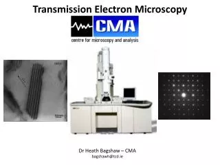
Transmission Electron Microscopy Visualization Techniques
Transmission Electron Microscopy Visualization Techniques. Bob Ashley AAS SMFW 7-13-2013. Reading List. Reading List Negative Staining 1990 Hayat and Miller

Transmission Electron Microscopy Visualization Techniques
E N D
Presentation Transcript
Transmission Electron Microscopy Visualization Techniques Bob Ashley AAS SMFW 7-13-2013
Reading List • Reading List • Negative Staining 1990 Hayat and Miller • Baker, T. S., and R. Henderson (2006). Electron cryomicroscopy. In "International Tables for Crystallography", Vol. F, ch. 19, pp. 451-463. Baker, T. S., and R. Henderson (2006). • Baker, T. S., N. H. Olson, and S. D. Fuller (2000) Erratum: Adding the third dimension to virus life cycles: Three-Dimensional reconstruction of icosahedral viruses from cryo-electron micrographs. Microbiol. Molec. Biol. Reviews64:237.
Overview • Free will vs. Determinism in electron microscopy • Two methods of viewing in TEM • Cryo and Negative Stain
Grids and Support Film • Usually Copper • How does it react with the specimen? • Mesh indicates amount of open area • Higher number less open 50-1000 • We use 400 mesh square • Very thin films and specimens • Hexagonal shape openings • Very delicate • Even mild bend or buckle can cause distortion of specimen or focus aberration
Grid Types • Supports used must be strong yet electron transparent • Plastic (formvar) • Carbon • Holey carbon • Quantifoil • C-flat
Support Film Concerns • Mass thickness influences contrast while mechanical stability increases image clarity • Films in general must have • High transparency • Adequate strength to withstand E- beam and support specimen • Carbon coated only (6-10 nm) • Uniformly amorphous • More elastic scattering events with e- beam • Can be stable very thin 1-2nm • More stable than plastic alone • Hydrophobic, fragile, time consuming to make • Plastic only 10-20nm (10-20 nm) • Formvar • More clarity with less background than Carbon alone • Not as thermally stable and can cause charging and drift • Carbon Coated with Plastic • Stability of carbon but will have a thickness that may impede resolution
All Sides Being Equal? • Dull Side (coppery) • More area for film to adhere • Shiny side (polished) • Not as much surface area for films to adhere • Can cause movement under e- beam exposure
To Glow or Not Glow Discharge renders continuous carbon coated grids hydrophilic by applying a negative charge. • Aids stain spread more uniformly (increases wettability) • Helps particles in specimen to adhere to the substrate • Decreases likelihood of the virus particles being held in aggregates as a result of the interaction between the virus particles and the surface charge of film
Contrast • Two types in electron microscopy • Amplitude contrast (scattering contrast) • Subtractive effect where various shades are evident by loss of electrons • Main source of most electron microscope contrast (except cryo) • Phase Contrast (interference contrast) • Interference of diffracted waves cause intensity differences due to loss of energy and the corresponding shorter focal points • Appear as bright ring or halo around the edge of an object • Fresnel ‘freh-nell’ fringe
The Concept of Negative Stain • Heavy metal atoms act as barrier to the e- beam • Allows passage through specimen • Stain penetration into hydrophilic specimen • Dries faster than specimen • Mostly hydrated regions replacing water • Lipoproteins and proteins • Stains form around hydrophobic regions including lipid • Contrast dependent on stain thickness • Resolution range 20-40 Å
Negative Contrast • Dense areas are bright also exclude stain • Amplitude contrast • Areas with no stain appear light because there is nothing for the electron beam to hit and the transmitted electrons shine through
Simple Microscopy • Lighter areas have more protein and exclude stain • Darker areas are where the stain pools • Indent in support mechanism
Stain Film and Particle Interactions A. Hydrophilic specimen hydrophilic film B. Hydrophilic specimen on hydrophobic film C. Hydrophobic specimen on hydrophilic film D. Hydrophobic specimen on hydrophobic film
Negative and Positive Staining • Three types of staining visible • Negative staining appearing white • Negative staining appearing grey • Positive staining appearing black • Severe structural distortion A. 4% PTA Negative Stained B. 4% UA Positive Stained C. 4% UA Negative Stained
Factors Controlling Appearance • Specimen • pH • Isoelectric Point • Fixation • Concentration • Stain • pH • Charge • Buffer and specimen interaction • Osmolarity • Can influence structure and volume of particle • Interaction with the support mechanism • Grid film • Thickness of stain on film • Charge and beam interactions
The Effect of the Isoelectric Point of Protein and Stain • Isoelectric point (pI) or (IEP) • The pH at which a particular molecule or surface carries no net electrical charge • Can be time dependent and is not absolute • Fixation with glutaraldehyde increases net negative charge • The presence of a fixed negative or positive charge influences the deposition of any given stain • In general proteins • Combine (positive stain) with cations (UA+) on the alkaline side of the pI • Combine with anions (PTA-) on the acidic side of the pI • Protein pI • Stain pH greater than pI applies negative charge • Stain pH lower than pI applies positive charge • Ex. Protein with a pI of 5.0 is negatively charged at pH 7.0 with PTA- which is higher than the pI of the protein therefore the stain repels and is excluded by the protein
Other Effects of pH • Optimal pH for stains is not known but each has a satisfactory range • At high pH the stain penetration is usually enhanced with long stain time • At low pH the surface detail is usually highlighted due to acidic environment • May change with stain storage and with stain drying • Use fresh stain preferable and check before staining specimen Ex. stained with PTA at 5.0 pH, influenza virus surface spikes well preserved same sample stained with 7.5 pH PTA stain penetrates virus envelope Ex. PTA with pH of 4.5 recommended for resolving antibody particles bound to rotavirus
Negative Stains • Negative stain should: • Have minimal interaction with specimen (pos. stain) • High solubility in solution (precipitates and crystalizes in e- beam) • High density (must be at least twice the density of the specimen to be visualized) • High melting point to avoid beam damage • Small grain size • Chemical pH stability
Types of Stains • Uranyl Acetate+ (cation) • Most widely used • Density of 2.87 g/cm^3 • Ion diameter .4-.8 nm • pH of 4.0-5.5 (usually used at 4.5 unstable at 6.0) • Concentrations .5-5% ideal as 1% • Can act as fixative • Higher contrast than PTA • Stabilizes lipids therefore may minimize drying effect of virus particles • Uranyl Oxalate+(cation) • Can be used in pH from 5.0-7.0 (ideal at 6.5-6.8) • Desirable for pH sensitive specimens • Provides the contrast and penetration of UA without the acidity • Desirable for virus proteins below the pI or low molecular weight • Uranyl Formate+(cation) • Smallest grain size for better penetration of interstices of sample • Useful for high-res • pH of 4.0-5.5 (usually used around 4.5) • Density of 3.68 g/cm^3 • Ideal as .75%
Types of Stains Continued • PTA-(anion) • Along with UA most widely used • Density 4 g/cm^3 • Grain size of 1.2 nm (not useful for high res work) • At neutral pH very little interaction with the specimen (avoids most positive staining) • Very stable in e- beam • Will not fix a specimen • Not stable over time with storage <1 month • May dissociate quaternary proteins into small units • Ammonium Molybdate • Used for osmotically sensitive specimens • pH from 5.0-8.0 useful at 7.0-7.4 • Higher contrast than PTA • Methylamine Tungstate (NanoW) • pH 6.4-7.0 • Tolerates concentrated buffers
Drawbacks of Negative Stain • Fixation • Tends to concentrate sample • Cellular debris and other junk • Positive staining • Beam irradiation • Lower kV=more damage potential • Drying • Leads to distortion of particle • Flattening • Will usually happen perpendicular to support mechanism • Makes sample typically larger in diameter to known size
Negative Stain Cryo Cryo EM Contrast reversal of negative stain, dark areas indicate density- Phase Contrast Light areas indicate density • Cryo Fixation Advantages • Keeps sample in near native state • Higher resolution – 8-15 Å • No artifacts from stain
Types of Ice • Amorphous or glassy ice • Target state of cryoEM samples • Liquid nitrogen -195° C • Heat capacity too low- Liedenfrost Effect • Liquid ethane • Liquid propane • Cubic ice • Water in crystalline lattice obscures beam • Usually around -140° C • Vanilla Ice • Too hot to handle yet too cold to hold
Plunge Freezing Manual Blotting The Mechanism
Visualizing Ice on the Grid Search for suitable area on grid
Low Dose • Ice is beam sensitive • E- cause irradiated sample • High res data can be lost in a matter of seconds • Focus on area that is not photographed and correct for astigmatism • Keep levels to around 5-20 E/A^2 • Can be a software automated process
Defocus Tradeoff • Focus adjacent region of interest to true focus • No inherent contrast from sample in ice • No tone ring visible in FFT • Reset to range desirable -2 to -5 ųm
Drawbacks of Cryo EM • Low contrast • Expensive • Time intensive • Labor intensive • Beam irradiation • Lower kV=more damage potential • Low signal to noise ratio • Size limitation • Must be > 400kD for proper resolution • Smallest published to date is 260kD • Cryo negative stain as possible solution • Phase plates