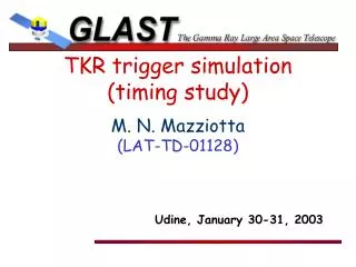
TKR trigger simulation (timing study)
Explore hardware design requirements, trigger timing simulations, and hit capture efficiency for TKR system. Includes GEANT 3.21 simulation, timing analysis, and preliminary results. Future plans for GLEAM and GLAST DIGI. Conclude with insights on trigger efficiency evaluation.

TKR trigger simulation (timing study)
E N D
Presentation Transcript
TKR trigger simulation (timing study) M. N. Mazziotta (LAT-TD-01128) Udine, January 30-31, 2003
Aim of this work • Requirements for the hardware design: • Trigger delay to latch the discriminator output • Trigger efficiency vs threshold and coincidence window • Hit capture efficiency vs delay and threshold • Applications: • Detector acceptance calculation • GRB time detection • 3. ....
Simulation code • GEANT 3.21: geometric description and tracking • 4 middle trays (4 x-z layers and 4 y-z layers) • HEED: Si energy loss and e-h pairs production • Front end electronics simulation (transfer function) • Induced current calculation (Ramo’s Theorem)
Timing studies Voltage Vth TOT T1 T2 time The threshold value has been set at a fraction of Vmip.
Trigger timing Trigger: 6-fold coincidence of the first 3 x-z and 3 y-z fired planes Coincidence window = 1 s (one shot) Tc (time coincidence) = the last T1 of the triggered planes Tf(trigger falling edge) = the first T2 of the triggered planes Time coincidence width = Tf-Tc
Trigger timing T1 T2 T1 T2 T1 T2 Tc Tf
Timing studies: 1 GeV muons Strip signals: Vth=1/4Vmip
Timing studies: 1 GeV muons Plane signals: OR of the strips in the plane
Timing studies: 1 GeV Plane signals: OR of the strips in the plane Two peaks!
Hit capture efficiency T2-Tc = time interval when the strip signal is over the threshold (respect to the trigger time Tc). Td = time interval between the trigger and the hit capture time (delay) The hit is “captured” if Td < T2-Tc The efficiency as a function of Td is evaluated from the cumulative distribution of T2-Tc 1 GeV muons have been simulated at zenith angles 0º, 10º,20º,30º,40º and uniformly distributed in azimuth
Hit capture efficiency: 1 GeV Trig to TKR Tc
Hit capture efficiency: 1 GeV =40°, =0° Trig to TKR Tc
Hit capture efficiency: 1 GeV =0°: threshold scanning Trig to TKR Tc
Hit capture efficiency: 1 GeV =40º:threshold scanning Trig to TKR Tc
Future plans GLEAM DIGIT (fired strips, ToT per layer) GLAST DIGI HIT (rin, rout, E) Timing analysis L1T TkrTrig
Preliminary results (2 GeV , =0°) Plane signals: OR of the strips in the plane
Preliminary results (2 GeV , =0°) Trig to TKR
Conclusions • A trigger timing study has been performed on a mini TKR tower consisting of 4 middle trays • The trigger hit capture efficiency has been also evaluated To evaluate the trigger efficiency a simulation on the whole TKR system is needed: GLEAM era! (people: M.N.M., M. B., F. L., F. G., N. G.)