FVTX Trigger Timing Study
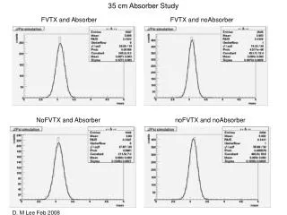
This study investigates the GL1 trigger timing and efficiency by analyzing the active width resulting from the input pulse phase scan. The plateau width is determined where 100% input pulse acceptance occurs, revealing that the active region varies based on the input pulse width. Measurements were taken on March 5, 2015, with input pulse widths of 50ns, 80ns, and 110ns. The results illustrate the relationship between pulse width and trigger timing, highlighting significant shifts in GL1 rates and the efficiency metrics related to varying test conditions.

FVTX Trigger Timing Study
E N D
Presentation Transcript
GL1 Active Width As a result of the GL1 input phase scan, the plateau width is measured where accepts 100% input pulse. The active region varies depending on the input pulse width.
Input Pulse Width=110ns March 5th, 2015 Working point 53.53 3/5/2015 ~ Efficiency = Visual Scaler before GL1 input/GL1 rates 72.6ns There was 1/8th BCLK shift between the measurements Blue an Orange dots .
Input Width=110ns March 5th, 2015 Working point 53.78 3/5/2015 ~ 96ns Phase is 110ns wider.
Phase Scan 1 (South) March 5th, 2015 GL1 rates [Hz] 50ns Input Pulse Width=50ns
Phase Scan 2 (North) 40ns Input Pulse Width=80ns
Phase Scan 3 (North) <10ns Input Pulse Width=50ns
Case 1 : Should issue trigger BCLK Input TTL GL1 Trigger Latch timing
Case 3 : shouldn’t issue trigger BCLK Input TTL × GL1 Trigger
Case 1 : Should issue trigger BCLK Input TTL GL1 Trigger
Default Time difference South North No custom delay between North and South. The difference was 40ns when this was measured. However, the timing can be shifted ± 1/8th BCLK.
After optimized timing March 5, 2015 North South
Trigger Timing at GL1 input North South MPC 4x4c April 12, 2015