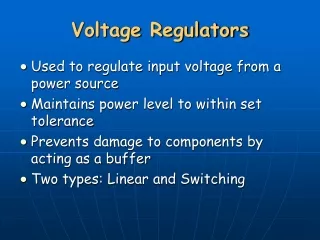
Switching-Mode Regulators
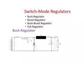
Switching-Mode Regulators. Convert an unregulated DC voltage into a regulated DC voltage. Buck Regulator. Output Voltage is Less Than the Input Voltage. BJT Chopper L-C Filter Load.

Switching-Mode Regulators
E N D
Presentation Transcript
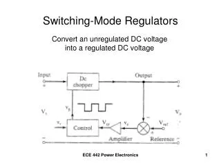
Switching-Mode Regulators Convert an unregulated DC voltage into a regulated DC voltage ECE 442 Power Electronics
Buck Regulator Output Voltage is Less Than the Input Voltage BJT Chopper L-C Filter Load Control Voltage Freewheeling Diode ECE 442 Power Electronics
Mode 1 Operation – Q1 switched ON Input current flows through L, C, and the Load – rises linearly ECE 442 Power Electronics
Mode 2 Operation – Q1 switched OFF Inductor current continues to flow through L, C, the Load, and Dm, falling linearly until Q1 is turned ON again. ECE 442 Power Electronics
Waveforms for the Buck Regulator ECE 442 Power Electronics
Summary for the Buck Regulator • The peak-to-peak ripple current is • The peak-to-peak ripple voltage is ECE 442 Power Electronics
Summary for continuous current case • The critical value of the inductor is • The critical value of the capacitor is ECE 442 Power Electronics
Boost Regulator Output Voltage is Greater Than the Input Voltage ECE 442 Power Electronics
Mode 1 Operation – M1 switched ON Input current flows through L and M1 (linearly) ECE 442 Power Electronics
Mode 2 Operation – M1 switched OFF Current that flowed through the transistor now flows through L, C, the Load, and diode Dm until transistor M1 is turned ON again. ECE 442 Power Electronics
Waveforms for the Boost Regulator ECE 442 Power Electronics
Summary for the Boost Regulator • The peak-to-peak ripple current is • The peak-to-peak ripple voltage is ECE 442 Power Electronics
Summary for continuous current case • The critical value of the inductor is • The critical value of the capacitor is ECE 442 Power Electronics
Buck-Boost Regulator The output voltage could be less than or greater than the input voltage The polarity of the output voltage is opposite to the polarity of the input voltage Vs – Inverting Regulator ECE 442 Power Electronics
Mode 1 Operation – Q1 turned ON Input current flows through inductor L and Q1 linearly. ECE 442 Power Electronics
Mode 2 Operation – Q1 switched OFF Current flowing through L now flows through L, C, Dm and the Load. ECE 442 Power Electronics
Waveforms for the Buck-Boost Regulator ECE 442 Power Electronics
Summary for the Buck-Boost Regulator • The peak-to-peak ripple current is • The peak-to-peak ripple voltage is ECE 442 Power Electronics
Summary for continuous current case • The critical value of the inductor is • The critical value of the capacitor is ECE 442 Power Electronics
Converter with a highly inductive Load Input Current is “pulse” shaped ECE 442 Power Electronics
Connect an input filter Filter out the converter-generated harmonics from the supply line. ECE 442 Power Electronics
Equivalent circuit for the converter-generated harmonic currents ECE 442 Power Electronics
Example 5.10 ECE 442 Power Electronics
Buck Chopper for PSpice Simulation ECE 442 Power Electronics
Results from PSpice ECE 442 Power Electronics
Fourier Coefficients of the input current ECE 442 Power Electronics
Example 5.10 in MultiSim7 ECE 442 Power Electronics
Fourier Coefficients of the Input Current ECE 442 Power Electronics