Download

1 / 22
220 likes | 259 Vues
Explore the detailed process of completing a microprocessor project using the MSP430F449PZ chip, from parts gathering to troubleshooting and programming, including construction steps and sensor integration.

E N D
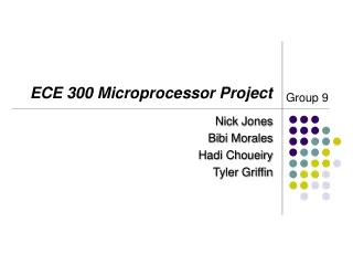
ECE 300 Microprocessor ProjectUsing The Texas Instruments MSP 430F449PZ Controller Group members: William Bohon Steve Bishop Ann Tan Marve Morrow
Project Overview • Project Assignment • Parts Gathering • First Group Meeting - Soldering Practice • Board Construction: • MSP430F449PZ Chip • Capacitors and Resistors
Project Overview • JTAG • More Components • LCD Display • Standoffs • Banana Jacks and Wires • Programming the chip • Troubleshooting • Temperature Sensor • Completed Board
Project Assignment • Students were assigned into groups and group leaders were selected. • The details of the project were explained to group leaders after the lecture in which it was assigned. • Project equipment, including microscope and soldering equipment, were given to each group for a limited amount of time. • Group leaders contacted their team and explained the project.
Parts Gathering • Parts were bought from the ECE parts store in Ferris Hall for $15. • MSP 430F449PZ samples were ordered online from Texas Instrument. • The most suitable sensor for the project was researched. • Samples of sensors were ordered online through the website: http://www.analog.com
Soldering Practice • Group members practiced soldering on a provided practice board with the extra MSP430 chip during the first group meeting. • A couple of capacitors were also used for practice.
Board Construction – MSP430 chip • The MSP430F449PZ chip was soldered first because it had the finest connections, and having other devices get in the way of its installation would have been difficult. • Flux was applied to the pin connection points, and the chip was carefully aligned with these pins using a microscope as aid. • Pins were first soldered at the corners for two reasons: • 1. To secure the aligned chip. • 2. To stop excess heat from damaging the chip.
Board Construction – Capacitors and Resistors • The 47k resistor was placed at R5. • The non-polarized capacitors were installed to the following positions with the following capacitance: • C1 with 0.1 μF • C2 with 0.1 μF • C4 with 0.1 μF • C5 with 0.1 μF • C9 with 1.0 μF • C10 with 0.1 μF
Board Construction – Capacitors and Resistors • The polarized capacitors were placed in C3 and C6, both having 10 μF capacitance. • The Polarized capacitors were installed after the JTAG connection was installed because this allowed power to run through the board. With the power, polarity could be found with a voltmeter. • The positive end was connected to the side of the capacitor with a dark stripe.
Board Construction – JTAG • The JTAG was installed by soldering the pins on the back side of the board. • A microscope was used to avoid soldering a connection between the pins and ground.
Board Construction – More Components • Other components were soldered to the board: • Power switch • Voltage Regulator • Five Volt Input Plus • Slider Switch • Time Crystal
Board Construction – LCD Display • Similar to the JTAG connector, this was soldered on the back side of the board with care to avoid shorting pins with the ground. • This was one of the last components installed because the screen is fragile.
Board Construction – Standoffs • The standoffs were installed into each corner. • This protects the back side of the board from being damaged by keeping the board off its supporting surface.
Board Construction – Banana Jacks • The banana jacks were drilled into the top right part of the board. • The red one was connected to Ja6, which goes to an analog data pin of the MSP430 chip. • The black one was connected to ground at Z3. Z3 was determined as ground by observing the lack of buffering between the port hole and the black ground on the back side of the board.
Board Construction – Wiring • Wires were used to connect the banana jacks to their ports • There was also a wire that grounded the resistors at C1, C2, and C3 to the port hole Z5.
Programming the Chip • The files lcd.c, lcd.h, delay.c, delay.h, demo.c, sensor.c. were copied to a computer directory from the ECE 300 website. • The 27–pin cable connector of the FET (Flash Emulation Kit) was connected to the parallel port of a computer, and the 14-pin connector was connected to the JTAG port in order to program the chip. • Procedures shown in the manual were followed.
Troubleshooting • Our demo test message “888808888” revealed that some of our LCD pixels were not showing up. The steps below were done for troubleshooting: • Connections of the LCD on the board , and the MSP430 on the board were checked. • The cause was identified when the dead pixels lit up when pressure was applied to the pin connections on the right side of the MSP430 chip. • The problem was solved by re-soldering some connections to these loose pin connections.
Temperature Sensor • The AD22103KT from Analog Devices. • This temperature sensor has three pins, as shown:
Temperature Sensor • The sensor was hooked up in the following manner: • Vo to the red banana jack (port Ja6) • Vs to TP3 VCC (determined to be a 2.85 V source) • GND to the black banana jack (Port Z3) • An additional wire was soldered to port TP3 VCC for the Vs connection.
Temperature Sensor • The formula for “sample” in sensor.c had to be modified in order to correctly output temperature. • It initially output voltage. • Using the formula below from the data sheet, the equation was found to be: • TA = (41.35 * Vout – 8.929) degrees C • Where Vs is 2.85 V, and Vout was the previous formula in sensor.c.
Temperature Sensor • TA = (41.35 * Vout – 8.929) degrees C • In the actual formula written to sensor.c, 8.929 is multiplied by 100 because the program shifts the decimal place to the left by two. This was not needed in multiplying Vout because it was already adjusted for the shifting.